|
|
|
PDF HI-539 Data sheet ( Hoja de datos )
| Número de pieza | HI-539 | |
| Descripción | Precision/ 4-Channel/ Low-Level/ Differential Multiplexer | |
| Fabricantes | Intersil Corporation | |
| Logotipo | ||
Hay una vista previa y un enlace de descarga de HI-539 (archivo pdf) en la parte inferior de esta página. Total 11 Páginas | ||
|
No Preview Available !
Data Sheet
HI-539
July 1999 File Number 3149.2
Precision, 4-Channel, Low-Level,
Differential Multiplexer
The Intersil HI-539 is a monolithic, 4-Channel, differential
multiplexer. Two digital inputs are provided for channel
selection, plus an Enable input to disconnect all channels.
Performance is guaranteed for each channel over the
voltage range ±10V, but is optimized for low level differential
signals. Leakage current, for example, which varies slightly
with input voltage, has its distribution centered at zero input
volts.
In most monolithic multiplexers, the net differential offset due
to thermal effects becomes significant for low level signals.
This problem is minimized in the HI-539 by symmetrical
placement of critical circuitry with respect to the few heat
producing devices.
Supply voltages are ±15V and power consumption is only
2.5mW.
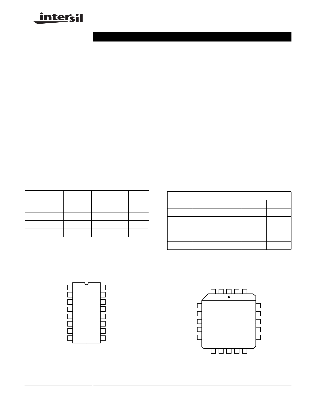
Ordering Information
PART NUMBER
HI1-0539-5
HI1-0539-8
TEMP.
RANGE (oC)
PACKAGE
0 to 75 16 Ld CERDIP
-55 to 125 16 Ld CERDIP
HI3-0539-5
HI4P0539-5
0 to 75
0 to 75
16 Ld PDIP
20 Ld PLCC
PKG.
NO.
F16.3
F16.3
E16.3
N20.35
Pinouts
HI-539
(CERDIP, PDIP)
TOP VIEW
A0 1
EN 2
V- 3
IN 1A 4
IN 2A 5
IN 3A 6
IN 4A 7
OUT A 8
16 A1
15 GND
14 V+
13 IN 1B
12 IN 2B
11 IN 3B
10 IN 4B
9 OUT B
Features
• Differential Performance, Typical:
- Low ∆rON, 125oC . . . . . . . . . . . . . . . . . . . . . . . . . . 5.5Ω
- Low ∆ID(ON), 125oC . . . . . . . . . . . . . . . . . . . . . . . 0.6nA
- Low ∆ Charge Injection . . . . . . . . . . . . . . . . . . . . 0.1pC
- Low Crosstalk . . . . . . . . . . . . . . . . . . . . . . . . . . . -124dB
• Settling Time, ±0.01% . . . . . . . . . . . . . . . . . . . . . . . 900ns
• Wide Supply Range . . . . . . . . . . . . . . . . . . . ±5V to ±18V
• Break-Before-Make Switching
• No Latch-Up
Applications
• Low Level Data Acquisition
• Precision Instrumentation
• Test Systems
TRUTH TABLE
ON CHANNEL TO
EN
A1
A0
OUT A
OUT B
L
X
X
None
None
H L L 1A 1B
H L H 2A 2B
H H L 3A 3B
H H H 4A 4B
HI-539
(PLCC)
TOP VIEW
3 2 1 20 19
V- 4
IN 1A 5
NC 6
IN 2A 7
IN 3A 8
18 V+
17 IN 1B
16 NC
15 IN 2B
14 IN 3B
9 10 11 12 13
1 CAUTION: These devices are sensitive to electrostatic discharge; follow proper IC Handling Procedures.
http://www.intersil.com or 407-727-9207 | Copyright © Intersil Corporation 1999
1 page 
HI-539
Test Circuits and Waveforms Unless Otherwise Specified TA = 25oC, V+ = +15V, V- = -15V, VAH = 4V and VAL = 0.8V (Continued)
10
ID(ON)
1
HI-539†
EN 0.8V
OUT A
A ID(OFF)
ID(OFF) = IS(OFF)
25 50 75 100 125
TEMPERATURE (oC)
FIGURE 2A. LEAKAGE CURRENT vs TEMPERATURE
HI-539†
±10V
A0 A1
† Similar Connection For Side “B”
10V
FIGURE 2B. ID(OFF) TEST CIRCUIT (NOTE 6)
HI-539†
A IS(OFF)
OUT A
0.8V
EN
±10V
10V
A0
A1
† Similar Connection For Side “B”
OUT A
A0 A1 EN
10V
A ID(ON)
±10V
4V
†Similar Connection For Side “B”
FIGURE 2C. IS(OFF) TEST CIRCUIT (NOTE 6)
FIGURE 2D. ID(ON) TEST CIRCUIT (NOTE 6)
NOTE:
6. Three measurements = ±10V, 10V, and 0V.
FIGURE 2. LEAKAGE CURRENT
14
12
10
8
6
4
2
0
100Hz
FUNCTIONAL LIMIT
VSUPPLY = ±15V
VSUPPLY = ±10V
1kHz
10kHz
100kHz
TOGGLE FREQUENCY
1MHz 3MHz 10MHz
+15V/+10V
A +ISUPPLY
VA 50Ω
V+
A1
IN
HI-539 †
1A
A0 IN 2A
IN 3A
+10V/+5V
IN 4A
-10V/-5V
5V EN OUT A
GND V-
HIGH = 4.0V
VA
LOW = 0V
50% DUTY CYCLE
10MΩ
A -ISUPPLY
14pF
-15V/-10V
†Similar Connection For Side “B”
FIGURE 3A. SUPPLY CURRENT vs TOGGLE FREQUENCY
FIGURE 3B. TEST CIRCUIT
FIGURE 3. DYNAMIC SUPPLY CURRENT
5
5 Page 
HI-539
Die Characteristics
DIE DIMENSIONS:
92 mils x 100 mils
METALLIZATION:
Type: AlCu
Thickness: 16kÅ ±2kÅ
SUBSTRATE POTENTIAL (NOTE):
-VSUPPLY
PASSIVATION:
Type: Nitride Over Silox
Nitride Thickness: 3.5kÅ ±1kÅ
Silox Thickness: 12kÅ ±2.0kÅ
WORST CASE CURRENT DENSITY:
2.54 x 10⁵ A/cm2 at 20mA
TRANSISTOR COUNT:
236
PROCESS:
CMOS-DI
NOTE: The substrate appears resistive to the -VSUPPLY terminal, therefore it may be left floating (Insulating Die Mount) or it may be mounted on a
conductor at -VSUPPLY potential.
Metallization Mask Layout
HI-539
V- EN A0
A1 GND
V+
IN1A
IN2A
IN1B
IN2B
IN3A
IN4A
OUTA
OUTB
IN4B IN3B
All Intersil semiconductor products are manufactured, assembled and tested under ISO9000 quality systems certification.
Intersil semiconductor products are sold by description only. Intersil Corporation reserves the right to make changes in circuit design and/or specifications at any time with-
out notice. Accordingly, the reader is cautioned to verify that data sheets are current before placing orders. Information furnished by Intersil is believed to be accurate and
reliable. However, no responsibility is assumed by Intersil or its subsidiaries for its use; nor for any infringements of patents or other rights of third parties which may result
from its use. No license is granted by implication or otherwise under any patent or patent rights of Intersil or its subsidiaries.
For information regarding Intersil Corporation and its products, see web site http://www.intersil.com
11
11 Page | ||
| Páginas | Total 11 Páginas | |
| PDF Descargar | [ Datasheet HI-539.PDF ] | |
Hoja de datos destacado
| Número de pieza | Descripción | Fabricantes |
| HI-539 | Precision/ 4-Channel/ Low-Level/ Differential Multiplexer | Intersil Corporation |
| Número de pieza | Descripción | Fabricantes |
| SLA6805M | High Voltage 3 phase Motor Driver IC. |
Sanken |
| SDC1742 | 12- and 14-Bit Hybrid Synchro / Resolver-to-Digital Converters. |
Analog Devices |
|
DataSheet.es es una pagina web que funciona como un repositorio de manuales o hoja de datos de muchos de los productos más populares, |
| DataSheet.es | 2020 | Privacy Policy | Contacto | Buscar |