|
|
|
PDF AUIRF7749L2TR Data sheet ( Hoja de datos )
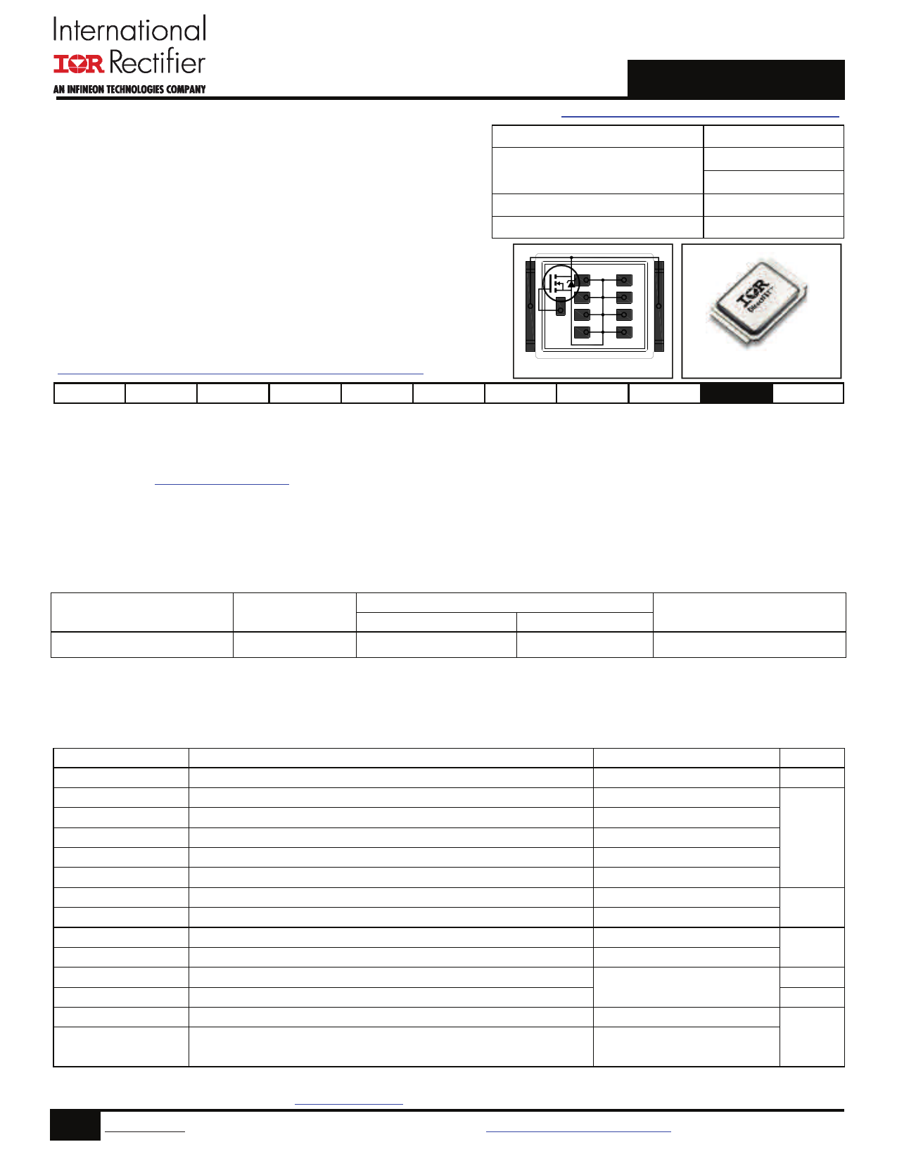
| Número de pieza | AUIRF7749L2TR | |
| Descripción | Power MOSFET ( Transistor ) | |
| Fabricantes | International Rectifier | |
| Logotipo | ||
Hay una vista previa y un enlace de descarga de AUIRF7749L2TR (archivo pdf) en la parte inferior de esta página. Total 12 Páginas | ||
|
No Preview Available !
AUTOMOTIVE GRADE
AUIRF7749L2TR
Advanced Process Technology
Optimized for Automotive Motor Drive, DC-DC and
other Heavy Load Applications
Exceptionally Small Footprint and Low Profile
High Power Density
Low Parasitic Parameters
Dual Sided Cooling
175°C Operating Temperature
Repetitive Avalanche Allowed up to Tjmax
Lead Free, RoHS Compliant and Halogen Free
Automotive Qualified *
Automotive DirectFET® Power MOSFET
V(BR)DSS
RDS(on) typ.
max.
ID (Silicon Limited)
Qg
60V
1.1m
1.5m
345A
183nC
DG
S
S
S
S
S
S
SD
S
Applicable DirectFET® Outline and Substrate Outline
L8 DirectFET2 L-can
SB SC
M2 M4
L4 L6 L8
Description
The AUIRF7749L2 combines the latest Automotive HEXFET® Power MOSFET Silicon technology with the advanced DirectFET® packaging technology
to achieve exceptional performance in a package that has the footprint of a D-Pak (TO-252AA) and only 0.7mm profile. The DirectFET® package is
compatible with existing layout geometries used in power applications, PCB assembly equipment and vapor phase, infra-red or convection soldering
techniques, when application note AN-1035 is followed regarding the manufacturing methods and processes. The DirectFET® package allows dual
sided cooling to maximize thermal transfer in automotive power systems.
This HEXFET® Power MOSFET is designed for applications where efficiency and power density are of value. The advanced DirectFET® packaging
platform coupled with the latest silicon technology allows the AUIRF7749L2 to offer substantial system level savings and performance improvement
specifically in motor drive, DC-DC and other heavy load applications on ICE, HEV and EV platforms. This MOSFET utilizes the latest processing
techniques to achieve ultra low on-resistance per silicon area. Additional features of this MOSFET are 175°C operating junction temperature and high
repetitive peak current capability. These features combine to make this MOSFET a highly efficient, robust and reliable device for high current
automotive applications.
Base Part Number
AUIRF7749L2
Package Type
DirectFET®
Standard Pack
Form
Quantity
Tape and Reel
4000
Orderable Part Number
AUIRF7749L2TR
Absolute Maximum Ratings
Stresses beyond those listed under “Absolute Maximum Ratings” may cause permanent damage to the device. These are stress ratings only; and
functional operation of the device at these or any other condition beyond those indicated in the specifications is not implied. Exposure to absolute-
maximum-rated conditions for extended periods may affect device reliability. The thermal resistance and power dissipation ratings are measured under
board mounted and still air conditions. Ambient temperature (TA) is 25°C, unless otherwise specified.
VGS
ID @ TC = 25°C
ID @ TC = 100°C
ID @ TA = 25°C
ID @ TC = 25°C
IDM
PD @TC = 25°C
PD @TA = 25°C
EAS
EAS (Tested)
IAR
EAR
TP
TJ
TSTG
Parameter
Gate-to-Source Voltage
Continuous Drain Current, VGS @ 10V
Continuous Drain Current, VGS @ 10V
Continuous Drain Current, VGS @ 10V
Continuous Drain Current, VGS @ 10V (Package limit)
Pulsed Drain Current
Power Dissipation
Power Dissipation
Single Pulse Avalanche Energy (Thermally Limited)
Single Pulse Avalanche Energy
Avalanche Current
Repetitive Avalanche Energy
Peak Soldering Temperature
Operating Junction and
Storage Temperature Range
HEXFET® is a registered trademark of International Rectifier.
*Qualification standards can be found at http://www.irf.com/
Max.
60
345
243
36
375
1380
341
3.8
315
714
See Fig. 16, 17, 18a, 18b
270
-55 to + 175
Units
V
A
W
mJ
A
mJ
°C
1 www.irf.com © 2015 International Rectifier
Submit Datasheet Feedback
August 10, 2015
1 page 
4.5
4.0
3.5
3.0
2.5
ID = 250µA
ID = 1.0mA
2.0 ID = 1.0A
1.5
-75 -50 -25 0 25 50 75 100 125 150 175
TJ , Temperature ( °C )
Fig. 7 Typical Threshold Voltage vs.
320
TJ = 25°C
240
160 TJ = 175°C
80
0
0
VDS = 5.0V
380µs PULSE WIDTH
20 40 60 80 100 120 140 160 180
ID, Drain-to-Source Current (A)
Fig 9. Typical Forward Trans conductance vs. Drain Current
16
ID= 120A
12 VDS= 48V
VDS= 30V
VDS= 12V
8
4
0
0 40 80 120 160 200 240
QG Total Gate Charge (nC)
Fig 11. Typical Gate Charge vs.
Gate-to-Source Voltage
5 www.irf.com © 2015 International Rectifier
AUIRF7749L2TR
10000
1000
100
TJ = 175°C
10
TJ = 25°C
1
0.1
0.2
VGS = 0V
0.4 0.6 0.8 1.0 1.2
VSD, Source-to-Drain Voltage (V)
1.4
Fig 8. Typical Source-Drain Diode Forward Voltage
100000
10000
VGS = 0V, f = 1 MHZ
Ciss = C gs + Cgd, C ds SHORTED
Crss = Cgd
Coss = Cds + Cgd
Ciss
Coss
1000
Crss
100
0.1
1 10
VDS, Drain-to-Source Voltage (V)
100
Fig 10. Typical Capacitance vs. Drain-to-Source Voltage
350
300
250
200
150
100
50
0
25
50 75 100 125 150
TC , CaseTemperature (°C)
175
Fig 12. Maximum Drain Current vs. Case Temperature
Submit Datasheet Feedback
August 10, 2015
5 Page 
AUIRF7749L2TR
Qualification Information†
Qualification Level
Moisture Sensitivity Level
ESD
Machine Model
Human Body Model
RoHS Compliant
Automotive
(per AEC-Q101)
Comments: This part number(s) passed Automotive qualification. IR’s
Industrial and Consumer qualification level is granted by extension of the
higher Automotive level.
DirectFET2 L-CAN
MSL1
Class M4 (+/- 800V)††
AEC-Q101-002
Class H2 (+/- 4000V)††
AEC-Q101-001
Yes
† Qualification standards can be found at International Rectifier’s web site: http//www.irf.com/
†† Highest passing voltage.
Click on this section to link to the appropriate technical
paper.
Click on this section to link to the Direct FET® Website.
Surface mounted on 1 in. square Cu board, steady state.
TC measured with thermocouple mounted to top (Drain)
of part.
Repetitive rating; pulse width limited by max. junction
temperature.
Limited by TJmax, Starting TJ = 25°C, L = 0.044mH,
RG = 50, IAS = 120A.
Pulse width 400µs; duty cycle 2%.
Used double sided cooling, mounting pad with large
heat sink.
Mounted on minimum footprint full size board with
metalized back and with small clip heat sink.
R is measured at TJ of approximately 90°C.
11 www.irf.com © 2015 International Rectifier
Submit Datasheet Feedback
August 10, 2015
11 Page | ||
| Páginas | Total 12 Páginas | |
| PDF Descargar | [ Datasheet AUIRF7749L2TR.PDF ] | |
Hoja de datos destacado
| Número de pieza | Descripción | Fabricantes |
| AUIRF7749L2TR | Power MOSFET ( Transistor ) | International Rectifier |
| Número de pieza | Descripción | Fabricantes |
| SLA6805M | High Voltage 3 phase Motor Driver IC. |
Sanken |
| SDC1742 | 12- and 14-Bit Hybrid Synchro / Resolver-to-Digital Converters. |
Analog Devices |
|
DataSheet.es es una pagina web que funciona como un repositorio de manuales o hoja de datos de muchos de los productos más populares, |
| DataSheet.es | 2020 | Privacy Policy | Contacto | Buscar |