|
|
|
PDF SY5810 Data sheet ( Hoja de datos )
| Número de pieza | SY5810 | |
| Descripción | Single Stage Flyback And PFC Controller | |
| Fabricantes | Silergy | |
| Logotipo | ||
Hay una vista previa y un enlace de descarga de SY5810 (archivo pdf) en la parte inferior de esta página. Total 18 Páginas | ||
|
No Preview Available !
Applications Note: SY5810
Single Stage Flyback And PFC Controller
With Primary Side Control For LED Lighting
Preliminary datasheet
General Description
The SY5810 is a single stage Flyback and PFC
controller targeting at LED lighting applications. It is a
primary side controller without applying any secondary
feedback circuit for low cost, and drives the Flyback
converter in the quasi-resonant mode to achieve higher
efficiency. It keeps the Flyback converter in constant
on time operation to achieve high power factor.
Ordering Information
SY5810 □(□□)□
Temperature Code
Package Code
Optional Spec Code
Temperature Range: -40°C to 85°C
Ordering Number Package type Note
SY5810ABC
SOT23-6
----
Features
• Primary side control eliminates the opto-coupler.
• Valley turn-on of the primary MOSFET to achieve
low switching losses
• 0.3V primary current sense reference voltage leads
to a lower sense resistance thus a lower conduction
loss.
• Internal high current MOSFET driver: 0.25A
sourcing and 0.5A sinking
• Low start up current: 15µA typical
• Reliable short LED and Open LED protection
• Power factor >0.90 with single-stage conversion.
• Compact package: SOT23-6
Applications
• LED lighting
• Down light
• Tube lamp
• PAR lamp
• Bulb
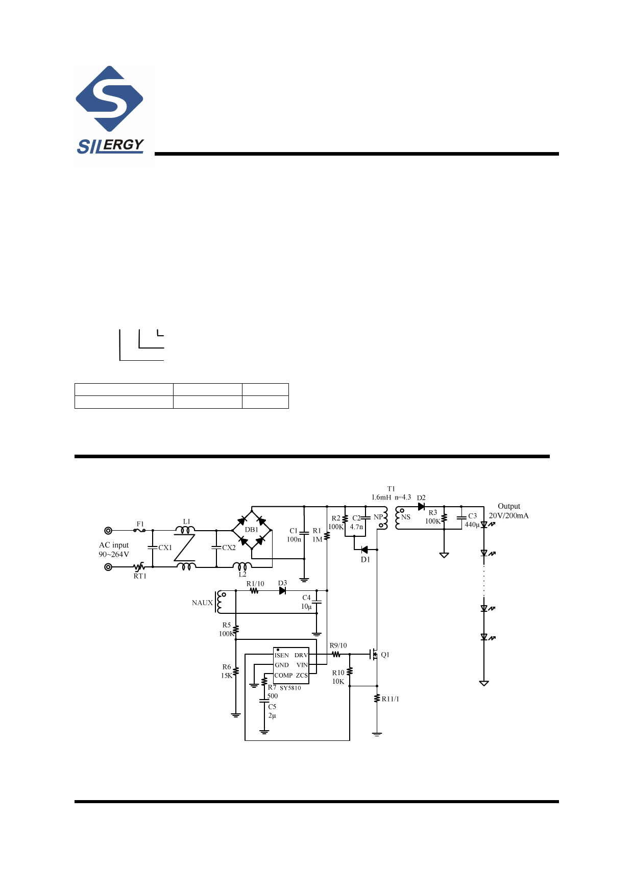
Typical Applications
Figure 1. Schematic Diagram SOT23-6
AN_SY5810 Rev0.1A
Silergy Corp. Confidential- Prepared for Customer Use Only 1
1 page 
SY5810
Operation
SY5810 is a constant current Flyback controller with
primary side control and PFC function that targets at
LED lighting applications.
The Device provides primary side control to eliminate the
opto-couplers or the secondary feedback circuits, which
would cut down the cost of the system.
High power factor is achieved by constant on operation
mode, with which the control scheme and the circuit
structure are both simple.
In order to reduce the switching losses and improve EMI
performance, Quasi-Resonant switching mode is applied,
which means to turn on the power MOSFET at voltage
valley; the start up current of SY5810 is rather small
(15uA typically) to reduce the standby power loss further;
the maximum switching frequency is clamped to 120kHz
to reduce switching losses and improve EMI performance
when the converter is operated at light load condition.
SY5810 provides reliable protections such as Short
Circuit Protection (SCP), Open LED Protection (OLP),
Over Temperature Protection (OTP), etc.
SY5810 is available with STO23-6
Applications Information
Start up
After AC supply or DC BUS is powered on, the capacitor
CVIN across VIN and GND pin is charged up by BUS
voltage through a start up resistor RST. Once VVIN rises up
to VVIN-ON, the internal blocks start to work. VVIN will be
pulled down by internal consumption of IC until the
auxiliary winding of Flyback transformer could supply
enough energy to maintain VVIN above VVIN-OFF.
The whole start up procedure is divided into two sections
shown in Fig.4. tSTC is the CVIN charged up section, and
tSTO is the output voltage built-up section. The start up
time tST composes of tSTC and tSTO, and usually tSTO is
much smaller than tSTC.
Fig.4 Start up
The start up resistor RST and CVIN are designed by rules
below:
(a) Preset start-up resistor RST, make sure that the current
through RST is larger than IST and smaller than IVIN_OVP
VBUS
IVIN_OVP
<R ST
<
VBUS
IST
(1)
Where VBUS is the BUS line voltage.
(b) Select CVIN to obtain an ideal start up time tST, and
ensure the output voltage is built up at one time.
CVIN
=
(
VBUS
RST
-IST ) ×
VVIN_ON
t ST
(2)
(d) If the CVIN is not big enough to build up the output
voltage at one time. Increase CVIN and decrease RST, go
back to step (a) and redo such design flow until the ideal
start up procedure is obtained.
Internal pre-charge design for quick start up
After VVIN exceeds VVIN,ON, VCOMP is pre-charged by an
internal current source. The PWM block won’t start to
output PWM signals until VCOMP is over the initial
voltage VCOMP,IC, which can be programmed by RCOMP.
Such design is meant to reduce the start up time shown in
Fig.5.
The voltage pre-charged VCOMP_IC in start-up procedure
can be programmed by RCOMP
VCOMP_IC =600mV-300µA × R COMP (3)
AN_SY5810Rev0.1A Silergy Corp. Confidential- Prepared for Customer Use Only 5
5 Page 
Design Example
A design example of typical application is shown below step by step.
#1. Identify design specification
Design Specification
VAC(RMS)
IOUT
90V~264V
200mA
#2. Transformer design (NPS, LM)
Refer to Power Device Design
VOUT
η
20V
85%
Conditions
VAC,MIN
△VS
POUT
CDrain
90V
50V
4W
100pF
(a)Compute turns ratio NPS first
VAC-MAX
VMOS-(BR)DS
VD,F
fS-MIN
264V
600V
1V
75kHz
NPS
≤
VMOS_(BR)DS
× 90%- 2VAC_MAX -∆VS
VOUT +VD,F
= 600V × 0.9- 2 × 264V-50V
20V+1V
=5.54
NPS is set to
NPS =4.2
(b)fS,MIN is preset
fS_MIN =75kHz
(c) Compute the switching period tS and ON time t1 at the peak of input voltage.
1
tS = fS_MIN =13.3µs
t1 =
tS × NPS × (VOUT +VD_F )
2VAC_MIN +NPS × (VOUT +VD_F )
= 13.3µs × 4.2 × (20V+1V)
2 × 90V+4.2× (20V+1V)
=5.464µs
(d) Compute the inductance LM
SY5810
AN_SY5810Rev0.1A Silergy Corp. Confidential- Prepared for Customer Use Only 11
11 Page | ||
| Páginas | Total 18 Páginas | |
| PDF Descargar | [ Datasheet SY5810.PDF ] | |
Hoja de datos destacado
| Número de pieza | Descripción | Fabricantes |
| SY5810 | Single Stage Flyback And PFC Controller | Silergy |
| SY5814A | Single Stage Buck PFC Controller | Silergy |
| Número de pieza | Descripción | Fabricantes |
| SLA6805M | High Voltage 3 phase Motor Driver IC. |
Sanken |
| SDC1742 | 12- and 14-Bit Hybrid Synchro / Resolver-to-Digital Converters. |
Analog Devices |
|
DataSheet.es es una pagina web que funciona como un repositorio de manuales o hoja de datos de muchos de los productos más populares, |
| DataSheet.es | 2020 | Privacy Policy | Contacto | Buscar |