|
|
|
PDF UB262 Data sheet ( Hoja de datos )
| Número de pieza | UB262 | |
| Descripción | 1-CELL LITHIUM-ION/POLYMER BATTERY PROTECTION IC | |
| Fabricantes | Unisonic Technologies | |
| Logotipo | ||
Hay una vista previa y un enlace de descarga de UB262 (archivo pdf) en la parte inferior de esta página. Total 10 Páginas | ||
|
No Preview Available !
UNISONIC TECHNOLOGIES CO., LTD
UB262
Preliminary
1-CELL LITHIUM-ION/POLYMER
BATTERY PROTECTION IC
CMOS IC
DESCRIPTION
The UTC UB262 is a series of lithium-ion / lithium-polymer
rechargeable battery protection ICs incorporating high accuracy
voltage detection circuits and delay circuits.
The UTC UB262 is suitable for protection of single cell lithium-ion /
lithium polymer battery packs from overcharge, over discharge and
over current.
The ultra-small package and less required external components
make it ideal to integrate the UTC UB262 into the limited space of
battery pack.
54
6
1 23
SOT-26
FEATURES
* High-accuracy voltage detection circuit
Overcharge detection voltage: 4.250~4.350V, Accuracy: ±50Mv
Overcharge release voltage: 4.050~4.150V, Accuracy: ±50mV
Overdischarge detection voltage: 2.30~2.90V, Accuracy: ±100mV
Overdischarge release voltage: 2.90~3.00V, Accuracy: ±100mV
Discharge overcurrent detection voltage: 150mV, Accuracy: ±30mV
Short-circuiting detection voltage: 0.85V (fixed), Accuracy: ±300mV
* Delay times are generated by an internal circuit (external capacitors are unnecessary)
Overcharge delay time: 100ms (typ.)
Overdischarge delay time: 25ms (typ.)
Discharg e overcurrent delay time: 10ms (typ.)
Short circuit delay time: 500μs (typ.)
* Low current consumption (Products with Power-down Function)
Operation mode: 3.0μA typ., 6.0μA max. (VDD=3.9V)
Ultra low power-down current: 0.1μA max. (VDD=2.0V)
* High-withstanding-voltage device is used for charger connection pins (CS pin and OC pin: Absolute maximum
rating=20V)
* 0 V battery charge function “available” / “unavailable” are selectable.
* Wide operating temperature range: -40°C~+85°C
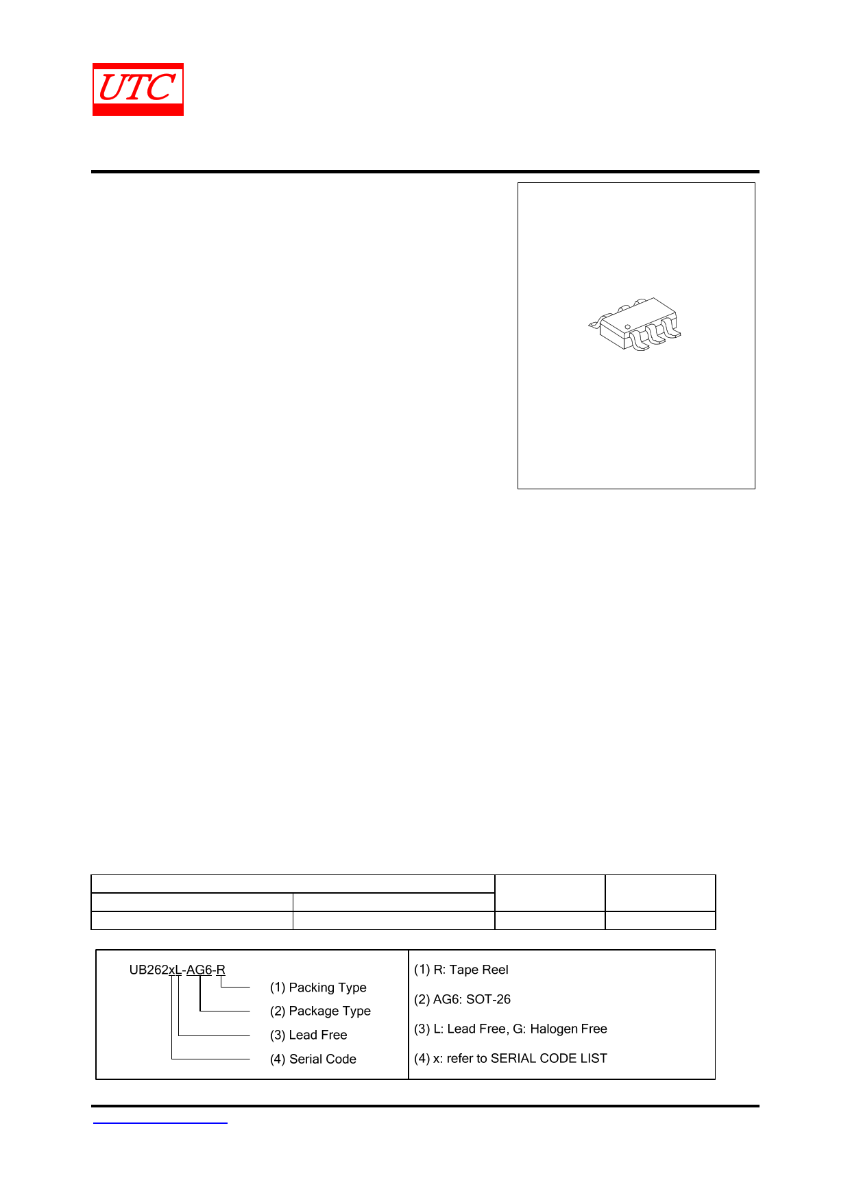
ORDERING INFORMATION
Note:
Ordering Number
Lead Free
Halogen Free
UB262xL-AG6-R
UB262xG-AG6-R
xx: Output Voltage, refer to Marking Information.
Package
SOT-26
Packing
Tape Reel
www.unisonic.com.tw
Copyright © 2014 Unisonic Technologies Co., Ltd
1 of 10
QW-R502-A92.a
1 page 
UB262
Preliminary
CMOS IC
OPERATION
1. Normal Condition
The UTC UB262 series monitors the voltage of the battery connected between VDD pin and VSS pin and the
voltage difference between CS pin and VSS pin to control charging and discharging. When the battery voltage is in
the range from the overdischarge detection voltage (VDL) to the overcharge detection voltage (VCU), and the CS pin
voltage is in the range from the charger detection voltage (VCHA) to the overcurrent detection voltage (VDIOV), the IC
turns both the charging and discharging control FETs on. This condition is called the normal condition, and in this
condition charging and discharging can be carried out freely.
Note: When a battery is connected to the IC for the first time, discharging may not be enabled. In this case, short
the CS pin and VSS pin or connect the charger to restore the normal condition.
2. Overcurrent Condition
When a battery in the normal status is in the status where the voltage of the CS pin is equal to or higher than the
overcurrent detection voltage because the discharge current is higher than the specified value and the status lasts
for the overcurrent detection delay time, the discharge control FET is turned off and discharging is stopped. This
status is called the overcurrent status. In the overcurrent status, the CS and VSS pins are shorted by the resistor
between CS and VSS (RVMS) in the IC. However, the voltage of the CS pin is at the VDD potential due to the load as
long as the load is connected. When the load is disconnected, the CS pin returns to the VSS potential. This IC detects
the status when the impedance between the EB+ pin and EB- pin (Refer to the typical application circuit) increases
and is equal to the impedance that enables automatic restoration and the voltage at the CS pin returns to
overcurrent detection voltage (VDIOV) or lower and the overcurrent status is restored to the normal status.
Note: The impedance that enables automatic restoration varies depending on the battery voltage and the set
value of overcurrent detection voltage.
3. Overcharge Condition
When the battery voltage becomes higher than the overcharge detection voltage (VCU) during charging under the
normal condition and the detection continues for the overcharge detection delay time (tCU), the UTC UB262 series
turns the charging control FET off to stop charging. This condition is called the overcharge condition. The overcharge
condition is released by the following two cases:
(1) When the battery voltage falls below the overcharge release voltage (VCL), the UTC UB262 series turns the
charging control FET on and turns to the normal condition.
(2) When a load is connected and discharging starts, the UTC UB262 series turns the charging control FET on
and returns to the normal condition. Just after the load is connected and discharging starts, the discharging current
flows through the parasitic diode in the charging control FET. At this moment the CS pin potential becomes Vf, the
voltage for the parasitic diode, higher than VSS level. When the battery voltage goes under the overcharge detection
voltage (VCU) and provided that the CS pin voltage is higher than the overcurrent detection voltage, the UTC UB262
series releases the overcharge condition.
Note 1: If the battery is charged to a voltage higher than the overcharge detection voltage (VCU) and the battery
voltage does not fall below the overcharge detection voltage (VCU) even when a heavy load is connected, the
detection of overcurrent , load shortcircuiting do not function until the battery voltage falls below over charge
detection voltage (VCU). Since an actual battery has an internal impedance of several dozens of mΩ, the battery
voltage drops immediately after a heavy load that causes overcurrent is connected, and the detection of overcurrent
and load short-circuiting function.
Note 2: When a charger is connected after the overcharge detection, the overcharge condition is not released
even if the battery voltage is below the overcharge release voltage (VCL). The overcharge condition is released when
the CS pin voltage goes over the charger detection voltage (VCHA) by removing the charger.
UNISONIC TECHNOLOGIES CO., LTD
www.unisonic.com.tw
5 of 10
QW-R502-A92.a
5 Page | ||
| Páginas | Total 10 Páginas | |
| PDF Descargar | [ Datasheet UB262.PDF ] | |
Hoja de datos destacado
| Número de pieza | Descripción | Fabricantes |
| UB261 | 1-CELL LITHIUM-ION/POLYMER BATTERY PROTECTION IC | Unisonic Technologies |
| UB262 | 1-CELL LITHIUM-ION/POLYMER BATTERY PROTECTION IC | Unisonic Technologies |
| UB264A | LION BATTERY PROTECTION IC | Unisonic Technologies |
| UB264B | LION BATTERY PROTECTION IC | Unisonic Technologies |
| Número de pieza | Descripción | Fabricantes |
| SLA6805M | High Voltage 3 phase Motor Driver IC. |
Sanken |
| SDC1742 | 12- and 14-Bit Hybrid Synchro / Resolver-to-Digital Converters. |
Analog Devices |
|
DataSheet.es es una pagina web que funciona como un repositorio de manuales o hoja de datos de muchos de los productos más populares, |
| DataSheet.es | 2020 | Privacy Policy | Contacto | Buscar |