|
|
|
PDF 1SMC5370 Data sheet ( Hoja de datos )
| Número de pieza | 1SMC5370 | |
| Descripción | SURFACE MOUNT SILICON ZENER DIODE | |
| Fabricantes | TRSYS | |
| Logotipo | ||
Hay una vista previa y un enlace de descarga de 1SMC5370 (archivo pdf) en la parte inferior de esta página. Total 5 Páginas | ||
|
No Preview Available !
1SMC5348 THRU 1SMC5388
SURFACE MOUNT SILICON ZENER DIODE
VOLTAGE - 11 TO 200 Volts Power - 5.0 Watts
FEATURES
l For surface mounted applications in order to
optimize board space
l Low profile package
l Built-in strain relief
l Glass passivated junction
l Low inductance
l Typical ID less than 1 A above 13V
l High temperature soldering :
260 /10 seconds at terminals
l Plastic package has Underwriters Laboratory
Flammability Classification 94V-O
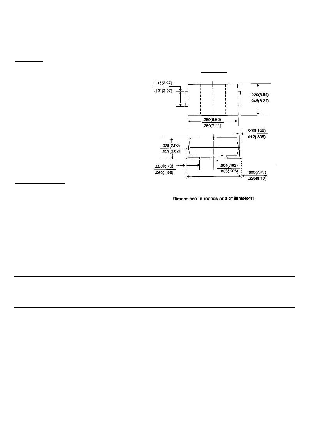
DO-214AB
MECHANICAL DATA
Case: JEDEC DO-214AB Molded plastic
over passivated junction
Terminals: Solder plated, solderable per
MIL-STD-750, method 2026
Standard Packaging: 16mm tape(EIA-481)
Weight: 0.007 ounce, 0.21 gram
MAXIMUM RATINGS AND ELECTRICAL CHARACTERISTICS
Ratings at 25 ambient temperature unless otherwise specified.
DC Power Dissipation @ TL=75 , Measure at Zero Lead Length(Fig. 1)
Derate above 75 (Note 1)
Peak forward Surge Current 8.3ms single half sine-wave superimposed on rated
load(JEDEC Method) (Note 1,2)
Operating Junction and Storage Temperature Range
SYMBOL
PD
IFSM
TJ,TSTG
VALUE
5.0
40.0
See Fig. 5
UNITS
Watts
mW/
Amps
-55 to +150
NOTES:
1. Mounted on 8.0mm2 copper pads to each terminal.
2. 8.3ms single half sine-wave, or equivalent square wave, duty cycle = 4 pulses per minute maximum.
1 page 
APPLICATION NOTE:
Since the actual voltage available from a given zener
diode is temperature dependent, it is necessary to
determine junction temperature under any set of
operating conditions in order to calculate its value. The
following procedure is recommended:
Lead Temperature, TL, should be determined from:
TL = LAPD + TA
LA is the lead-to-ambient thermal resistance ( /W)
and PD is the power dissipation.
Junction Temperature, TJ , may be found from:
TJ = TL + TJL
TJL is the increase in junction temperature above the
lead temperature and may be found from Figure 3 for a
train of power pulses or from Figure 4 for dc power.
TJL = JLPD
For worst-case design, using expected limits of Iz, limits
of PD and the extremes of TJ( TJ) may be estimated.
Changes in voltage, Vz, can then be found from:
V = VZ TJ
VZ, the zener voltage temperature coefficient, is fount
from Figures 2.
Under high power-pulse operation, the zener voltage will
vary with time and may also be affected significantly be
the zener resistance. For best regulation, keep current
excursions as low as possible.
Data of Figure 3 should not be used to compute surge
capability. Surge limitations are given in Figure 5. They
are lower than would be expected by considering only
junction temperature, as current crowding effects cause
temperatures to be extremely high in small spots
resulting in device degradation should the limits of
Figure. 5 be exceeded.
5 Page | ||
| Páginas | Total 5 Páginas | |
| PDF Descargar | [ Datasheet 1SMC5370.PDF ] | |
Hoja de datos destacado
| Número de pieza | Descripción | Fabricantes |
| 1SMC5370 | SURFACE MOUNT SILICON ZENER DIODE(VOLTAGE - 11 TO 200 Volts Power - 5.0 Watts) | Pan Jit International Inc. |
| 1SMC5370 | SURFACE MOUNT SILICON ZENER DIODE | TRSYS |
| 1SMC5371 | SURFACE MOUNT SILICON ZENER DIODE(VOLTAGE - 11 TO 200 Volts Power - 5.0 Watts) | Pan Jit International Inc. |
| 1SMC5371 | SURFACE MOUNT SILICON ZENER DIODE | TRSYS |
| Número de pieza | Descripción | Fabricantes |
| SLA6805M | High Voltage 3 phase Motor Driver IC. |
Sanken |
| SDC1742 | 12- and 14-Bit Hybrid Synchro / Resolver-to-Digital Converters. |
Analog Devices |
|
DataSheet.es es una pagina web que funciona como un repositorio de manuales o hoja de datos de muchos de los productos más populares, |
| DataSheet.es | 2020 | Privacy Policy | Contacto | Buscar |