|
|
|
PDF MT7910 Data sheet ( Hoja de datos )
| Número de pieza | MT7910 | |
| Descripción | High Brightness LED Driver | |
| Fabricantes | Maxic Technology | |
| Logotipo | ||
Hay una vista previa y un enlace de descarga de MT7910 (archivo pdf) en la parte inferior de esta página. Total 10 Páginas | ||
|
No Preview Available !
MT7910
High Brightness LED Driver
DESCRIPTION
The MT7910 is a hysteresis current mode control
LED driver IC. The MT7910 operates in constant
off-time mode. It allows efficient operation of
High Brightness (HB) LEDs from voltage sources
ranging from 14VDC up to 450VDC or 85VAC ~
265VAC. The MT7910 includes a PWM dimming
input that can accept an external control signal
with a duty ratio of 0 - 100% and a frequency of
up to a few kilohertz. It also includes a 0 - 245mV
linear dimming input which can be used both for
linear dimming and temperature compensation of
the LED current.
The MT7910 is ideally suited for buck LED
drivers. Since the MT7910 operates in hysteresis
current mode control, the controller achieves
good output current regulation without the need
for any loop compensation. Further, with Maxic
proprietary control technology (patent pending),
MT7910 achieves precision output current
accuracy from 85VAC ~ 265VAC. PWM dimming
response is limited only by the rate of rise and
fall of the inductor current, enabling very fast rise
and fall times.
Frequency jittering is used to reduce the EMI.
FEATURES
• Proprietary constant-current control. Great
LED current accuracy.
• Wide input range from 14VDC to 450VDC or
85VAC to 265VAC
• Application from a few mA to more than 1A
output
• Up to 92% efficiency
• Up to hundreds of LEDs
• Linear and PWM dimming capability
• Requires few external components for
operation
• Temperature compensation to regulate LED
current
• Embedded Over-temperature, LED open
circuit, LED short-circuit protection
• SOP-8 package
APPLICATION
• DC/DC or AC/DC LED driver applications
• RGB backlighting LED driver
• General purpose constant current source
• Signal and decorative LED lighting
• E14/E27/PAR30/PAR38/GU10 LED lamp
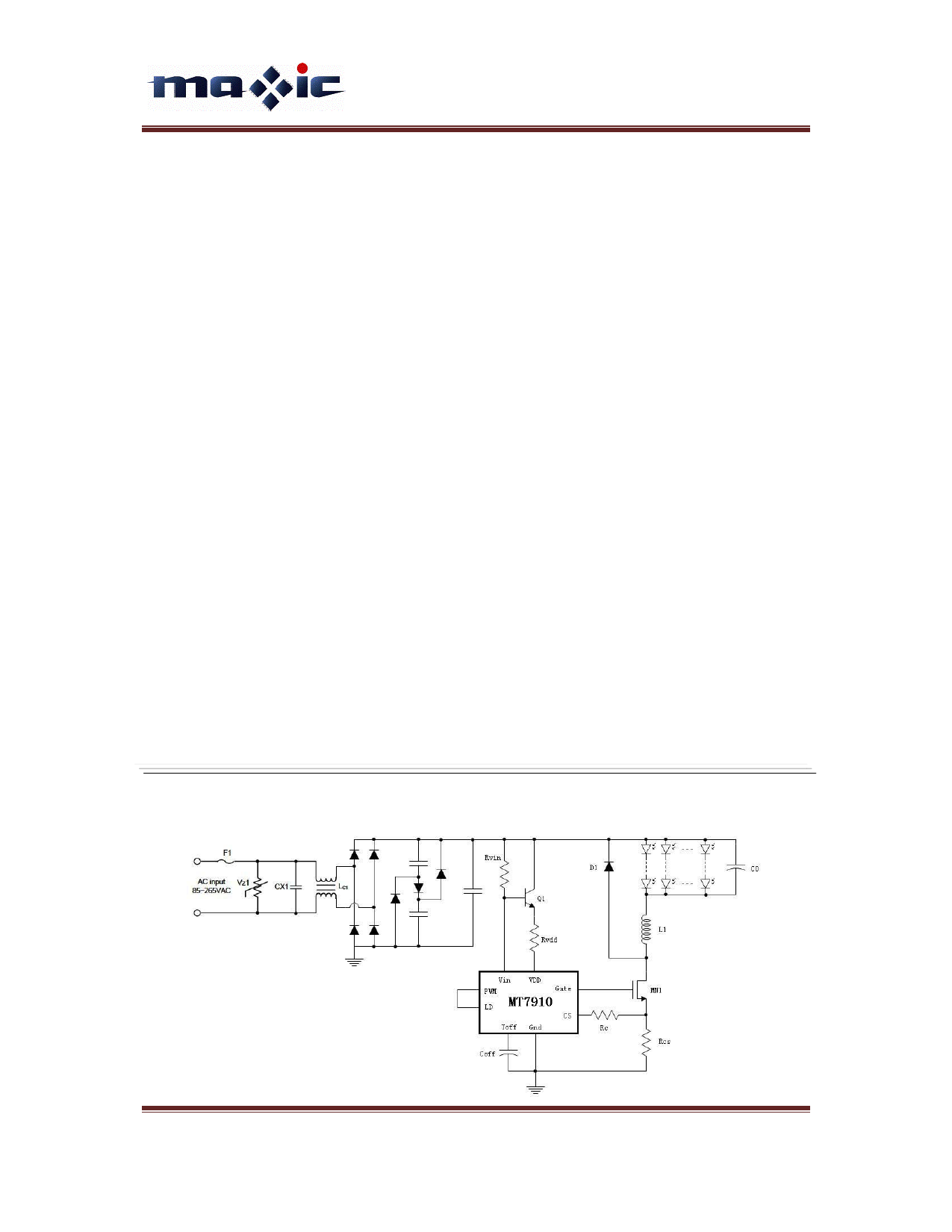
TYPICAL APPLICATION CIRCUIT
MT7910 Rev. 2.0
www.maxictech.com
Copyright © 2009 Maxic Technology Corporation
Page 1
1 page 
external MOSFET).
IVDD ≈ 0.5mA + QG • fS
Where fS is the switching frequency and QG is the
GATE charge of the external MOSFET (which
can be obtained from the datasheet of the
MOSFET).
Input voltage further applied through a suitable
resistor to VIN pin (Pin5), MT7910 clamped VIN
pin at 12V. This regulated voltage can be used to
bias the base or gate of the NPN or NMOS
transistor, which provides power to the VDD pin.
Further more, MT7910 detects the line voltage
VDC through VIN pin and compensates the line
voltage variation. Combined with the peak
current at CS pin control scheme, the accuracy
of the LED current is greatly improved and
almost insensitive to input voltage variation.
Current Sense
The current sense input of the MT7910 goes to
the noninverting inputs of two comparators. The
inverting terminal of one comparator is tied to an
internal 245mV (for BIN2, BIN1 is 217mV, BIN3
is 269mV) reference, whereas the inverting
terminal of the other comparator is connected to
the LD pin. The outputs of both comparator are
fed into an OR gate and the output of the OR
gate is fed into the reset pin of the flip-flop. Thus,
the comparator which has the lowest voltage at
the inverting terminal determines when the GATE
output is turned off.
The outputs of the comparator also includes a
typical 430ns blanking tie which prevents
spurious turn-offs of the external MOSFET due to
the turn-on spike normally present in peak
current mode control. In rare cases, this internal
blanking time might not be enough to filter out
the turn-on spike. In these case, an external RC
filter needs to be added between the external
sense resistor (RCS) and the CS pin.
MT7910
High Brightness LED Driver
Please note that the comparators are relatively
fast with a typical 80ns response time. A proper
layout minimizing external inductances will
prevent false triggering of these comparators.
Oscillator
Reference to Fig.1, the oscillator in the MT7910
is controlled by the capacitor connected at TOFF
pin and series resistor connected to CS pin.
Fig.1 Setup Toff time
First the charge current is determined by RC and
RCS, calculated as:
I off
=
185mV
(RC + RCS )
≈ 185mV
RC
Where, normally RCS << RC. Typically, RC=10KΩ,
Ioff = 18.5uA.
Then, Toff time of the oscillator is given by:
Toff
= Coff • 2V
I off
≈ Coff • RC • 2V
185mV
= 10.8 • Coff
where Coff is in pF and Toff is in us.
As equation shows, the Toff time is determined
by external RC value. So the constant-off time is
accurately controlled and consistency.
Linear Dimming
The Linear Dimming pin (LD pin) is used to
control the LED current. An external voltage
between 50mV to 245mV can be applied to the
LD pin to adjust the LED current during operation.
There are two cases when it may be necessary
to use the Linear Dimming pin.
MT7910 Rev. 2.0
www.maxictech.com
Copyright © 2009 Maxic Technology Corporation
Page 5
5 Page | ||
| Páginas | Total 10 Páginas | |
| PDF Descargar | [ Datasheet MT7910.PDF ] | |
Hoja de datos destacado
| Número de pieza | Descripción | Fabricantes |
| MT7910 | High Brightness LED Driver | Maxic Technology |
| Número de pieza | Descripción | Fabricantes |
| SLA6805M | High Voltage 3 phase Motor Driver IC. |
Sanken |
| SDC1742 | 12- and 14-Bit Hybrid Synchro / Resolver-to-Digital Converters. |
Analog Devices |
|
DataSheet.es es una pagina web que funciona como un repositorio de manuales o hoja de datos de muchos de los productos más populares, |
| DataSheet.es | 2020 | Privacy Policy | Contacto | Buscar |