|
|
|
PDF SARS05 Data sheet ( Hoja de datos )
| Número de pieza | SARS05 | |
| Descripción | Auxiliary Switch Diode | |
| Fabricantes | Sanken | |
| Logotipo | ||
Hay una vista previa y un enlace de descarga de SARS05 (archivo pdf) en la parte inferior de esta página. Total 18 Páginas | ||
|
No Preview Available !
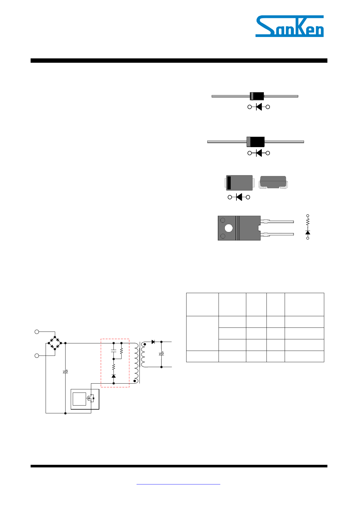
Auxiliary Switch Diode for Snubber
SARS01/02/05/10
Data Sheet
Description
SARS is the auxiliary switch diode for snubber circuit,
used in the primary side clamp snubber circuit of
switched-mode power supplies with fly back topology.
Since the ringing voltage at turning off the power
MOSFET is more reduced by the clamp snubber circuit
using SARS, the cross regulation of multi-outputs is
improved. Since some energy of the ringing is
transferred to the secondary side, the power supply
efficiency can be improved.
Package
SARS01 (Axial φ 2.7 / φ 0.60)
SARS02 (Axial φ 4 / φ 0.78)
Features
● Improving cross regulation
● Reducing noise
● Improving efficiency
Application
Switched-mode power supply (SMPS) with flyback
topology such as for the followings:
● White goods
● Adaptor
● Industrial equipment
Typical Application
Clamp snubber
CS RS1
RS2
SARS
SARS05 (SMA 4.5×2.6)
SARS10 (TO220F-2L)
Not to Scale
Lineup
● VRM=800V
RS2
External
component
Products
SARS01
IF (AVG)
VF
(max.)
1.2 A 0.92 V
Power supply
output power,
PO*
~50W
SARS02 1.5 A 0.92 V ~100W
SARS05 1 A 1.05 V ~50W
Built-in 22Ω SARS10 0.3 A 13 V
~300W
* PO is the reference value at selection. The temperature
of SARS should be measured based on actual
operation in the application.
Cont.
AC/DC converter IC
SARS01/02/05/10 - DSJ Rev.1.0 SANKEN ELECTRIC CO.,LTD.
Jun.29, 2015
http://www.sanken-ele.co.jp/en/
© SANKEN ELECTRIC CO.,LTD. 2015
1
1 page 
SARS01/02/05/10
3.1.3 Derating Curves (Tj = 150°C)
1.2
1.0
DC
0.8
0.6
0.4
0.2
0.0
100
110 120 130 140 150
Lead Temperature, TL (°C)
Figure 3-5 TL-IF(AV) (VR = 0 V)
3.2 SARS02
3.2.1 Typical Characteristics
100
10
1
TA = 150°C
0.1
0.01
TA = 25°C
TA = 100°C
0.001
0.0
0.5 1.0
Forward Voltage, VF (V)
Figure 3-7 VF-IF typical characteristics
1.5
1.2
1.0
Sine wave
0.8
DC
0.6
0.4
0.2
0.0
100
110 120 130 140 150
Lead Temperature, TL (°C)
Figure 3-6 TL-IF(AV) (VR = 800 V)
1.0E-03
1.0E-04
TA = 150°C
1.0E-05
1.0E-06
TA = 100°C
1.0E-07 TA = 25°C
1.0E-08
1.0E-09
0
200 400 600 800
Reverse Voltage, VR(V)
Figure 3-8 VR-IR typical characteristics
SARS01/02/05/10 - DSJ Rev.1.0 SANKEN ELECTRIC CO.,LTD.
Jun.29, 2015
http://www.sanken-ele.co.jp/en/
© SANKEN ELECTRIC CO.,LTD. 2015
5
5 Page 
SARS01/02/05/10
4.3 SARS05
SMA 4.5×2.6
YMDD
NOTES:
● Dimension is in millimeters.
● Pb-free. Device composition compliant with the RoHS directive.
4.4 SARS10
TO220F-2L
Part Number(AS05)
Lot Number
Y is the last digit of year (0 to 9)
M is the month (1 to 9, O, N or D)
DD is the date (two digit of 01 to 31)
Polarity marking (Cathode band)
SARS10
YMDD
Part Number
Lot Number
Y is the last digit of year (0 to 9)
M is the month (1 to 9, O, N or D)
DD is the date (two digit of 01 to 31)
12
NOTES:
● Dimension is in millimeters.
● Pb-free. Device composition compliant with the RoHS directive.
SARS01/02/05/10 - DSJ Rev.1.0 SANKEN ELECTRIC CO.,LTD.
Jun.29, 2015
http://www.sanken-ele.co.jp/en/
© SANKEN ELECTRIC CO.,LTD. 2015
11
11 Page | ||
| Páginas | Total 18 Páginas | |
| PDF Descargar | [ Datasheet SARS05.PDF ] | |
Hoja de datos destacado
| Número de pieza | Descripción | Fabricantes |
| SARS01 | Auxiliary Switch Diode | Sanken |
| SARS02 | Auxiliary Switch Diode | Sanken |
| SARS05 | Auxiliary Switch Diode | Sanken |
| Número de pieza | Descripción | Fabricantes |
| SLA6805M | High Voltage 3 phase Motor Driver IC. |
Sanken |
| SDC1742 | 12- and 14-Bit Hybrid Synchro / Resolver-to-Digital Converters. |
Analog Devices |
|
DataSheet.es es una pagina web que funciona como un repositorio de manuales o hoja de datos de muchos de los productos más populares, |
| DataSheet.es | 2020 | Privacy Policy | Contacto | Buscar |