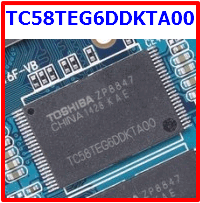
TC58TEG6DDKTA00 Datasheet PDF - Toshiba
| Part Number | TC58TEG6DDKTA00 | |
| Description | NAND memory Toggle DDR1.0 | |
| Manufacturers | Toshiba | |
| Logo |  |
|
|
There is a preview and TC58TEG6DDKTA00 download ( pdf file ) link at the bottom of this page. Total 30 Pages | ||
Preview 1 page No Preview Available !
TOSHIBA CONFIDENTIAL Tx58TEGxDDKTAx0
TOSHIBA
NAND memory
Toggle DDR1.0
Technical Data Sheet
Rev. 0.6
2013 – 07 – 10
TOSHIBA
Semiconductor & Storage Products
Memory Division
TC58TEG6DDKTA00 / TC58TEG6DDKTAI0
TH58TEG7DDKTA20 / TH58TEG7DDKTAK0
TH58TEG8DDKTA20 / TH58TEG8DDKTAK0
0
TENTATIVE 2013-07-10C
|
| |

TOSHIBA CONFIDENTIAL Tx58TEGxDDKTAx0
LIST of FIGURES
Figure 1. Block Diagram (TC58TEG6DDK) ............................................................................................................ 13
Figure 2. Block Diagram (TH58TEG7DDK) ........................................................................................................... 14
Figure 3. Block Diagram (TH58TEG8DDK) ........................................................................................................... 15
Figure 4. Overshoot/Undershoot Diagram .............................................................................................................. 18
Figure 5. tRISE and tFALL Definition for Output Slew Rate ...................................................................................... 25
Figure 6. ODT setting through ‘SET FEATURE’ .................................................................................................... 26
Figure 7. ODT enable/disable during Read ............................................................................................................. 26
Figure 8. ODT enable/disable during Write ............................................................................................................ 27
Figure 9. Functional Representation of ODT.......................................................................................................... 27
Figure 10. Write Protect timing requirements of the Program operation ............................................................. 28
Figure 11. Write Protect timing requirements of the Erase operation .................................................................. 28
Figure 12. Target Organization ............................................................................................................................... 29
Figure 13. Row Address Layout ............................................................................................................................... 30
Figure 14. Position of Plane Address ....................................................................................................................... 30
Figure 15. Area marked in first or last page of block indicating defect ................................................................. 32
Figure 16. Flow chart to create initial invalid block table...................................................................................... 33
Figure 17. Initialization Timing .............................................................................................................................. 34
Figure 18. Command Latch Cycle Timing............................................................................................................... 37
Figure 19. Address Latch Cycle Timing................................................................................................................... 37
Figure 20. Basic Data Input Timing........................................................................................................................ 38
Figure 21. Basic Data Output Timing ..................................................................................................................... 39
Figure 22. Read ID Operation Timing..................................................................................................................... 40
Figure 23. Status Read Cycle Timing ...................................................................................................................... 41
Figure 24. Set Feature Timing................................................................................................................................. 42
Figure 25. Get Feature Timing ................................................................................................................................ 42
Figure 26. Page Read Operation Timing ................................................................................................................. 43
Figure 27. Read Hold Operation with CE high..................................................................................................... 44
Figure 28. Page Program Operation Timing ........................................................................................................... 45
Figure 29. Command Latch Cycle Timing............................................................................................................... 46
Figure 30. Address Latch Cycle Timing................................................................................................................... 46
Figure 31. Basic Data Input Timing........................................................................................................................ 47
Figure 32. Basic Data Output Timing ..................................................................................................................... 47
Figure 33. Read ID Operation Timing..................................................................................................................... 48
Figure 34. Status Read Cycle Timing ...................................................................................................................... 49
Figure 35. Set Feature Timing................................................................................................................................. 50
Figure 36. Get Feature Timing ................................................................................................................................ 50
Figure 37. Page Read Operation Timing ................................................................................................................. 51
Figure 38. Page Program Operation Timing ........................................................................................................... 52
Figure 39. Page Read Timing................................................................................................................................... 59
Figure 40. Page Read with Random Data Output Timing ..................................................................................... 59
Figure 41. Data Out After Status Read Timing ...................................................................................................... 60
Figure 42. Sequential Cache Read Timing.............................................................................................................. 60
Figure 43. Random Cache Read Timing.................................................................................................................. 61
Figure 44. Random Data Output for Cache Read Timing ...................................................................................... 61
Figure 45. Page Program Timing............................................................................................................................. 62
Figure 46. Program operation with Random Data Input Timing .......................................................................... 62
Figure 47. Cache Program Timing........................................................................................................................... 63
Figure 48. Block Erase Timing ................................................................................................................................ 63
Figure 49. Copy-Back Program Timing ................................................................................................................... 64
Figure 50. Copy-Back Program with Random Data Input Timing ........................................................................ 64
Figure 51. Set Feature Timing................................................................................................................................. 65
Figure 52. Get Feature Timing ................................................................................................................................ 67
Figure 53. Read ID Timing....................................................................................................................................... 68
Figure 54. Read Status Timing ................................................................................................................................ 70
Figure 55. Reset timing............................................................................................................................................ 71
Figure 56. Reset timing during Program operation................................................................................................ 71
Figure 57. Reset timing during Erase operation..................................................................................................... 71
Figure 58. Reset timing during Read operation...................................................................................................... 71
Figure 59. Status Read after Reset operation ......................................................................................................... 72
TC58TEG6DDKTA00 / TC58TEG6DDKTAI0
TH58TEG7DDKTA20 / TH58TEG7DDKTAK0
TH58TEG8DDKTA20 / TH58TEG8DDKTAK0
4
TENTATIVE 2013-07-10C
Preview 5 Page |
Part DetailsOn this page, you can learn information such as the schematic, equivalent, pinout, replacement, circuit, and manual for TC58TEG6DDKTA00 electronic component. |
| Information | Total 30 Pages | |
| Link URL | [ Copy URL to Clipboard ] | |
| Product Image and Detail view |  1. - NAND memory Toggle DDR1.0 [ Learn More ] | |
| Download | [ TC58TEG6DDKTA00.PDF Datasheet ] | |
Share Link :
Electronic Components Distributor
|
An electronic components distributor is a company that sources, stocks, and sells electronic components to manufacturers, engineers, and hobbyists. |
| SparkFun Electronics | Allied Electronics | DigiKey Electronics | Arrow Electronics |
| Mouser Electronics | Adafruit | Newark | Chip One Stop |
Featured Datasheets
| Part Number | Description | MFRS |
| TC58TEG6DDKTA00 | The function is NAND memory Toggle DDR1.0. Toshiba | |
Semiconductors commonly used in industry:
1N4148 |
BAW56 |
1N5400 |
NE555 | | ||
Quick jump to:
TC58
1N4
2N2
2SA
2SC
74H
BC
HCF
IRF
KA | ||

