|
|
|
PDF AD7400A Data sheet ( Hoja de datos )
| Número de pieza | AD7400A | |
| Descripción | Isolated Sigma-Delta Modulator | |
| Fabricantes | Analog Devices | |
| Logotipo | ||
Hay una vista previa y un enlace de descarga de AD7400A (archivo pdf) en la parte inferior de esta página. Total 19 Páginas | ||
|
No Preview Available !
Preliminary Technical Data
Isolated Sigma-Delta Modulator
AD7400A
FEATURES
10 MHz clock rate
Second-order modulator
16 bits no missing codes
±2 LSB INL typical at 16 bits
3.5 µV/°C maximum offset drift
On-board digital isolator
On-board reference
Low power operation: 18 mA maximum at 5.25 V
−40°C to +125°C operating range
16-lead SOIC, 8-lead gull-wing surface mount DIP packages
AD7401A, external clock version
Safety and regulatory approvals
UL recognition
3750 V rms for 1 minute per UL 1577
CSA Component Acceptance Notice #5A
VDE Certificate of Conformity
DIN EN 60747-5-2 (VDE 0884 Part 2): 2003-01
DIN EN 60950 (VDE 0805): 2001-12; EN 60950: 2000
VIORM = 891 V peak
APPLICATIONS
GENERAL DESCRIPTION
The AD7400A1 is a second-order, Σ-Δ modulator that converts
an analog input signal into a high speed, 1-bit data stream with
on-chip digital isolation based on Analog Devices, Inc.
iCoupler® technology. The AD7400A operates from a 5 V power
supply and accepts a differential input signal of ±200 mV
(±320 mV full scale). The analog input is continuously sampled
by the analog modulator, eliminating the need for external
sample-and-hold circuitry. The input information is contained
in the output stream as a density of ones with a data rate of
10 MHz. The original information can be reconstructed with an
appropriate digital filter. The serial I/O can use a 5 V or a 3 V
supply (VDD2).
The serial interface is digitally isolated. High speed CMOS,
combined with monolithic air core transformer technology,
means the on-chip isolation provides outstanding performance
characteristics superior to alternatives such as optocoupler
devices. The part contains an on-chip reference. The AD7400A
is offered in a 16-lead SOIC and 8-lead gull-wing surface mount
DIP and has an operating temperature range of −40°C to
+125°C.
AC motor controls
Data acquisition systems
A/D + opto-isolator replacements
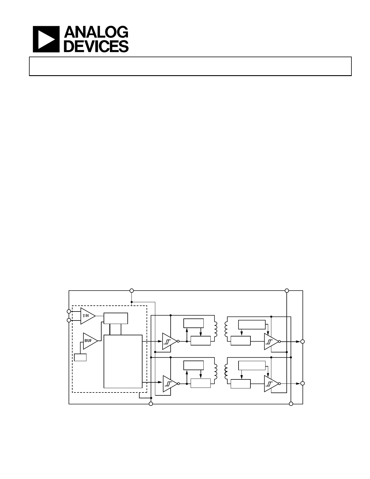
FUNCTIONAL BLOCK DIAGRAM
VDD1
VDD2
VIN+
VIN–
T/H
Σ-∆ ADC
BUF
REF
CONTROL LOGIC
UPDATE
ENCODE
UPDATE
AD7400A
WATCHDOG
DECODE
WATCHDOG
MDAT
ENCODE
DECODE
MCLKOUT
GND1
Figure 1.
GND2
1 Protected by U.S. Patents 5,952,849; 6,873,065; and 7,075,329. Other patents pending.
Rev. PrA
Information furnished by Analog Devices is believed to be accurate and reliable. However, no
responsibility is assumed by Analog Devices for its use, nor for any infringements of patents or other
rights of third parties that may result from its use. Specifications subject to change without notice. No
license is granted by implication or otherwise under any patent or patent rights of Analog Devices.
Trademarksandregisteredtrademarksarethepropertyoftheirrespectiveowners.
One Technology Way, P.O. Box 9106, Norwood, MA 02062-9106, U.S.A.
Tel: 781.329.4700
www.analog.com
Fax: 781.461.3113
©2008 Analog Devices, Inc. All rights reserved.
1 page 
Preliminary Technical Data
AD7400A
INSULATION AND SAFETY-RELATED SPECIFICATIONS
Table 3.
Parameter
Input-to-Output Withstand Momentary Withstand Voltage
Minimum External Air Gap (Clearance)
Minimum External Tracking (Creepage)
Minimum Internal Gap (Internal Clearance)
Tracking Resistance (Comparative Tracking Index)
Isolation Group
Symbol Value
Unit Conditions
VISO
3750 min V
1-minute duration
L(I01)
7.46 min mm Measured from input terminals to output
terminals, shortest distance through air
L(I02)
8.1 min
mm Measured from input terminals to output
terminals, shortest distance path along body
0.017 min mm Insulation distance through insulation
CTI >175 V DIN IEC 112/VDE 0303 Part 1
IIIa Material group (DIN VDE 0110, 1/89, Table 1)
REGULATORY INFORMATION
Table 4.
UL1
Recognized Under 1577
Component Recognition Program1
3750 V rms Isolation Voltage
File E214100
CSA
Approved under CSA Component
Acceptance Notice #5A
Reinforced insulation per
CSA 60950-1-03 and IEC 60950-1,
630 Vrms maximum working
voltage
File 205078
VDE2
Certified according to DIN EN 60747-5-2
(VDE 0884 Part 2): 2003-012
Basic insulation, 891 V peak
Complies with DIN EN 60747-5-2 (VDE 0884 Part 2): 2003-01,
DIN EN 60950 (VDE 0805): 2001-12; EN 60950: 2000
Reinforced insulation, 891 V peak
File 2471900-4880-0001
1 In accordance with UL 1577, each AD7400A is proof tested by applying an insulation test voltage ≥ 4500 V rms for 1 second (current leakage detection limit = 7.5 µA).
2 In accordance with DIN EN 60747-5-2, each AD7400A is proof tested by applying an insulation test voltage ≥ 1671 V peak for 1 second (partial discharge detection
limit = 5 pC).
Rev. PrA | Page 5 of 19
5 Page 
Preliminary Technical Data
1.0
BANDWIDTH = 100kHz
0.8
0.6
0.4
0.2
0
VIN DC INPUT (V)
Figure 19. RMS Noise Voltage vs. VIN DC Input
AD7400A
11.0
10.8
10.6
10.4
10.2
VDD1 = VDD2 = 4.5V
10.0
9.8
9.6 VDD1 = VDD2 = 5.25V
9.4 VDD1 = VDD2 = 5V
9.2
9.0
TEMPERATURE (°C)
Figure 20. MCLKOUT vs. Temperature for Various Supplies
Rev. PrA | Page 11 of 19
11 Page | ||
| Páginas | Total 19 Páginas | |
| PDF Descargar | [ Datasheet AD7400A.PDF ] | |
Hoja de datos destacado
| Número de pieza | Descripción | Fabricantes |
| AD7400 | Isolated Sigma-Delta Modulator | Analog Devices |
| AD7400A | Isolated Sigma-Delta Modulator | Analog Devices |
| Número de pieza | Descripción | Fabricantes |
| SLA6805M | High Voltage 3 phase Motor Driver IC. |
Sanken |
| SDC1742 | 12- and 14-Bit Hybrid Synchro / Resolver-to-Digital Converters. |
Analog Devices |
|
DataSheet.es es una pagina web que funciona como un repositorio de manuales o hoja de datos de muchos de los productos más populares, |
| DataSheet.es | 2020 | Privacy Policy | Contacto | Buscar |