|
|
|
PDF SL28EB742 Data sheet ( Hoja de datos )
| Número de pieza | SL28EB742 | |
| Descripción | EPROCLOCK GENERATOR | |
| Fabricantes | Silicon Laboratories | |
| Logotipo | ||
Hay una vista previa y un enlace de descarga de SL28EB742 (archivo pdf) en la parte inferior de esta página. Total 30 Páginas | ||
|
No Preview Available !
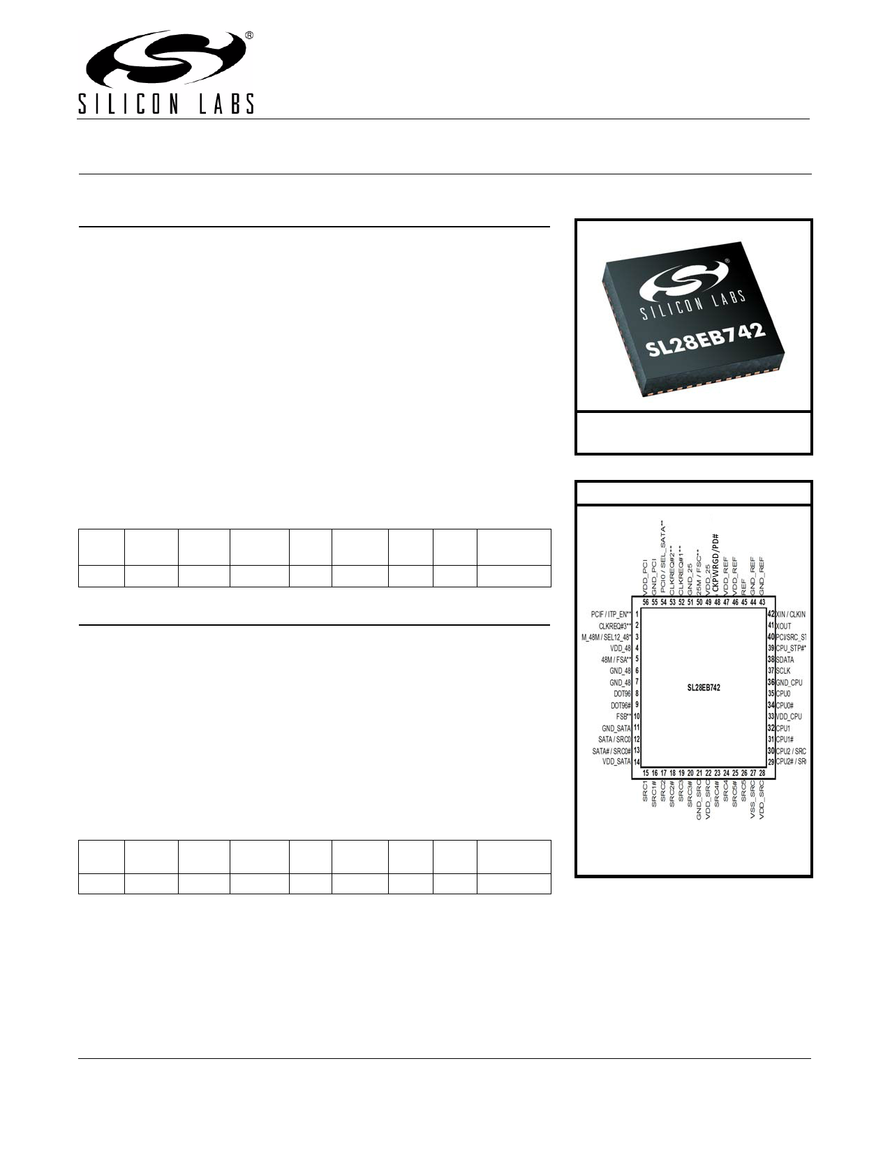
SL28EB742
EPROCLOCK® GENERATOR FOR INTEL® CK505 COMPLIANCE
Features
Compliant Intel CK505 Clock spec 25 MHz ouput
Low power push-pull type differential Buffered Reference Clock
output buffers
14.318 MHz
Integrated resistors on differential 14.318 MHz Crystal Input or Clock
clocks
input
Wireless friendly 3-bits slew rate
control on single-ended clocks
Differential CPU clocks with pin
selectable frequency
100 MHz Differential SRC clocks
I2C support with readback
capabilities
Triangular Spread Spectrum profile
for maximum electromagnetic
interference (EMI) reduction
Selectable Differential SATA or SRC Industrial Temperature:
clocks
96 MHz Differential DOT clock
48 MHz USB clock
Selectable 12 or 48 MHz clock
–40 to 85 °C
3.3 V power supply
56-pin QFN package
Selectable Differential SRC or CPU Clock
CPU SRC SATA DOT96 48M
x2/x3 x4/x7 x0/x1 x1 x1/2
48M/
12M
x1
33M 25M 14.318M
x2 x1
x1
EProClock® Programmable Technology
> 4000 bits of configurations
Can be configured through SMBus
or hard coded
Custom frequency sets
Differential skew control on true or
compliment or both
Differential duty cycle control on true
or compliment or both
Differential amplitude control
Differential and single-ended
slew rate control
Program Internal or External
series resistor on single-ended
clocks
Program different spread
profiles
Program different spread
modulation rate
Selectable Differential SRC or CPU Clock
CPU SRC
x2/x3 x4/x7
SATA DOT96 48M
x0/x1 x1 x1/2
48M/
12M
x1
33M 25M
x2 x1
14.318M
x1
Ordering Information:
See page 39
Pin Assignments
* Internal 100K-ohm pull-up resistor
** Internal 100K-ohm pull down resistor
Patents pending
Rev. 1.0 12/13
Copyright © 2013 by Silicon Laboratories
SL28EB742
This information applies to a product under development. Its characteristics and specifications are subject to change without notice.
1 page 
SL28EB742
Table 3. AC Electrical Specifications
Parameter
Long-term Accuracy
Clock Input
Symbol
Test Condition
Min Max Unit
LACC
Measured at VDD/2 differential
—
250 ppm
CLKIN Duty Cycle
CLKIN Rise and Fall Times
CLKIN Cycle to Cycle Jitter
CLKIN Long Term Jitter
Input High Voltage
Input Low Voltage
Input High Current
Input Low Current
CPU at 0.7 V
CPU Duty Cycle
83.33 MHz CPU Period
83.33 MHz CPU Period, SSC
TDC
TR/TF
TCCJ
TLTJ
VIH
VIL
IIH
IIL
Measured at VDD/2
Measured between 0.2 VDD and
0.8 VDD
Measured at VDD/2
Measured at VDD/2
XIN / CLKIN pin
XIN / CLKIN pin
XIN / CLKIN pin, VIN = VDD
XIN / CLKIN pin, 0 < VIN <0.8
47 53 %
0.5 4.0 V/ns
— 250 ps
350 ps
2 VDD+0.3 V
— 0.8 V
35 µA
–35 — µA
TDC
TPERIOD
TPERIODSS
Measured at 0 V differential 45 55
Measured at 0 V differential at 0.1s 11.99880 12.00120
Measured at 0 V differential at 0.1s 12.02887 12.03128
2
%
ns
ns
83.33 MHz CPU Absolute Period TPERIODAbs
Measured at 0 V differential at 11.18969 12.16344 ns
1clock
83.33 MHz CPU Absolute Period, TPERIODSSAbs Measured at 0 V differential at 1 11.89687 12.16344 ns
SSC
clock
100 MHz CPU Period
100 MHz CPU Period, SSC
100 MHz CPU Absolute Period
TPERIOD Measured at 0 V differential at 0.1s 9.99900 10.0010
TPERIODSS Measured at 0 V differential at 0.1s 10.02406 10.02607
TPERIODAbs
Measured at 0 V differential at
1clock
9.87400 10.1260
ns
ns
ns
100 MHz CPU Absolute Period, TPERIODSSAbs Measured at 0 V differential at
SSC
1 clock
9.87406 10.1762 ns
133 MHz CPU Period
133 MHz CPU Period, SSC
133 MHz CPU Absolute Period
TPERIOD Measured at 0 V differential at 0.1s 7.49925 7.50075
TPERIODSS Measured at 0 V differential at 0.1s 7.51804 7.51955
TPERIODAbs
Measured at 0 V differential at
1 clock
7.41425 7.58575
ns
ns
ns
133 MHz CPU Absolute period, TPERIODSSAbs Measured at 0 V differential at
SSC
1 clock
7.41430 7.62340 ns
Rev. 1.0
5
5 Page 
SL28EB742
2. Functional Description
2.1. Powerdown (PD#) Clarification
The CKPWRGD/PD# pin is a dual-function pin. During initial powerup, the pin functions as CKPWRGD. Once
CKPWRGD has been sampled high by the clock chip, the pin assumes PD# functionality. The PD# pin is an
asynchronous active low input used to shut off all clocks cleanly before shutting off power to the device. This signal
is synchronized internally to the device before powering down the clock synthesizer. PD# is also an asynchronous
input for powering up the system. When PD# is asserted low, clocks are driven to a low value and held before
turning off the VCOs and the crystal oscillator.
2.2. Powerdown (PD#) Assertion
When PD# is sampled low by two consecutive rising edges of CPUC, all single-ended outputs clocks will be held
low on their next high-to-low transition and differential clocks will be held low. When powerdown mode is desired as
the initial power on state, PD# must be asserted low in less than 10 µs after asserting CKPWRGD.
.
Table 6. Output Driver Status during CPU_STP and PCIS_STP#
Single-ended
Clocks
Stoppable
Non-stoppable
CPU_STP#
Asserted
Running
Running
PCI_STP#
Asserted
Driven low
Running
CLKREQ#
Asserted
Running
Running
SMBus OE
Disabled
Driven low
Differential Clocks Stoppable Clock driven high Clock driven high Clock driven low Clock driven low
Clock driven low Clock driven low Clock driven low
Non-stoppable
Running
Running
Running
PD# = 0 (Powerdown)
Table 7. Output Driver Status
All Single-ended Clocks
w/o Strap
w/ Strap
Low Hi-z
All Differential Clocks
Clock
Clock#
Low Low
Rev. 1.0
11
11 Page | ||
| Páginas | Total 30 Páginas | |
| PDF Descargar | [ Datasheet SL28EB742.PDF ] | |
Hoja de datos destacado
| Número de pieza | Descripción | Fabricantes |
| SL28EB742 | EPROCLOCK GENERATOR | Silicon Laboratories |
| Número de pieza | Descripción | Fabricantes |
| SLA6805M | High Voltage 3 phase Motor Driver IC. |
Sanken |
| SDC1742 | 12- and 14-Bit Hybrid Synchro / Resolver-to-Digital Converters. |
Analog Devices |
|
DataSheet.es es una pagina web que funciona como un repositorio de manuales o hoja de datos de muchos de los productos más populares, |
| DataSheet.es | 2020 | Privacy Policy | Contacto | Buscar |