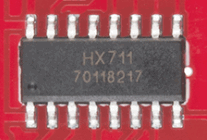
|
|
PDF HX711 Data sheet ( Hoja de datos )
| Número de pieza | HX711 | |
| Descripción | 24-Bit Analog-to-Digital Converter | |
| Fabricantes | Avia semiconductor | |
| Logotipo | ||
 1. 24-Bit ADC Converter - AVIA Hay una vista previa y un enlace de descarga de HX711 (archivo pdf) en la parte inferior de esta página. Total 9 Páginas | ||
|
No Preview Available !
HX711
24-Bit Analog-to-Digital Converter (ADC) for Weigh Scales
DESCRIPTION
Based on Avia Semiconductor’s patented
technology, HX711 is a precision 24-bit analog-
to-digital converter (ADC) designed for weigh
scales and industrial control applications to
interface directly with a bridge sensor.
The input multiplexer selects either Channel A
or B differential input to the low-noise
programmable gain amplifier (PGA). Channel A
can be programmed with a gain of 128 or 64,
corresponding to a full-scale differential input
voltage of ±20mV or ±40mV respectively, when
a 5V supply is connected to AVDD analog power
supply pin. Channel B has a fixed gain of 32. On-
chip power supply regulator eliminates the need
for an external supply regulator to provide analog
power for the ADC and the sensor. Clock input is
flexible. It can be from an external clock source, a
crystal, or the on-chip oscillator that does not
require any external component. On-chip power-
on-reset circuitry simplifies digital interface
initialization.
There is no programming needed for the
internal registers. All controls to the HX711 are
through the pins.
FEATURES
• Two selectable differential input channels
• On-chip active low noise PGA with selectable gain
of 32, 64 and 128
• On-chip power supply regulator for load-cell and
ADC analog power supply
• On-chip oscillator requiring no external
component with optional external crystal
• On-chip power-on-reset
• Simple digital control and serial interface:
pin-driven controls, no programming needed
• Selectable 10SPS or 80SPS output data rate
• Simultaneous 50 and 60Hz supply rejection
• Current consumption including on-chip analog
power supply regulator:
normal operation < 1.5mA, power down < 1uA
• Operation supply voltage range: 2.6 ~ 5.5V
• Operation temperature range: -40 ~ +85℃
• 16 pin SOP-16 package
APPLICATIONS
• Weigh Scales
• Industrial Process Control
Load cell
VAVDD
10uF
AVDD
INA+
INA-
R2 R1
VFB
S8550
BASE
Analog Supply Regulator
INB+
INB-
Input
MUX
24-bit Σ∆
ADC
PGA
Gain = 32, 64, 128
VSUP
VSUP DVDD
2.7~5.5V
Digital
Interface
DOUT
To/From
PD_SCK MCU
RATE
VBG
0.1uF
Bandgap Reference
AGND
Internal
Oscillator
HX711
XI XO
Fig. 1 Typical weigh scale application block diagram
TEL: (592) 252-9530 (P. R. China)
EMAIL: [email protected]
AVIA SEMICONDUCTOR
1 page 
HX711
Current Output Data
DOUT
PD_SCK
MSB
T2
T1
12
PD_SCK
PD_SCK
12
12
One conversion period
Next Output Data
T3
34
T4
34
LSB
24 25
24 25 26
Next Conversion:CH.A, Gain:128
Next Conversion:CH.B, Gain:32
34
24 25 26 27 Next Conversion:CH.B, Gain:64
Fig.2 Data output, input and gain selection timing and control
Symbol
Note
T1 DOUT falling edge to PD_SCK rising edge
T2 PD_SCK rising edge to DOUT data ready
T3 PD_SCK high time
T4 PD_SCK low time
MIN
0.1
0.2
0.2
TYP
1
1
MAX Unit
µs
0.1 µs
50 µs
µs
Reset and Power-Down
When chip is powered up, on-chip power on
rest circuitry will reset the chip.
Pin PD_SCK input is used to power down the
HX711. When PD_SCK Input is low, chip is in
normal working mode.
Power down:
PD_SCK
60µ s
Power down
Normal
Fig.3 Power down control
When PD_SCK pin changes from low to high
and stays at high for longer than 60µs, HX711
enters power down mode (Fig.3). When internal
regulator is used for HX711 and the external
transducer, both HX711 and the transducer will be
powered down. When PD_SCK returns to low,
chip will reset and enter normal operation mode.
After a reset or power-down event, input
selection is default to Channel A with a gain of
128.
Application Example
Fig.1 is a typical weigh scale application using
HX711. It uses on-chip oscillator (XI=0), 10Hz
output data rate (RATE=0). A Single power
supply (2.7~5.5V) comes directly from MCU
power supply. Channel B can be used for battery
level detection. The related circuitry is not shown
on Fig. 1.
AVIA SEMICONDUCTOR
5
5 Page | ||
| Páginas | Total 9 Páginas | |
| PDF Descargar | [ Datasheet HX711.PDF ] | |
Hoja de datos destacado
| Número de pieza | Descripción | Fabricantes |
| HX71 | Analog-to-Digital (A/D) converter | AVIA Semiconductor |
| HX710 | 24-bit analog / digital (A / D) converter chip | Avia semiconductor |
| HX710A | 24-Bit ADC | Avia semiconductor |
| HX710B | 24-Bit ADC | Avia semiconductor |
| Número de pieza | Descripción | Fabricantes |
| SLA6805M | High Voltage 3 phase Motor Driver IC. |
Sanken |
| SDC1742 | 12- and 14-Bit Hybrid Synchro / Resolver-to-Digital Converters. |
Analog Devices |
|
DataSheet.es es una pagina web que funciona como un repositorio de manuales o hoja de datos de muchos de los productos más populares, |
| DataSheet.es | 2020 | Privacy Policy | Contacto | Buscar |
