|
|
|
PDF MAX5813 Data sheet ( Hoja de datos )
| Número de pieza | MAX5813 | |
| Descripción | Ultra-Small Quad-Channel 8-/10-/12-Bit Buffered Output DACs | |
| Fabricantes | Maxim Integrated Products | |
| Logotipo | ||
Hay una vista previa y un enlace de descarga de MAX5813 (archivo pdf) en la parte inferior de esta página. Total 30 Páginas | ||
|
No Preview Available !
EVALUATION KIT AVAILABLE
MAX5813/MAX5814/MAX5815
Ultra-Small, Quad-Channel, 8-/10-/12-Bit Buffered
Output DACs with Internal Reference and I2C Interface
General Description
The MAX5813/MAX5814/MAX5815 4-channel, low-power,
8-/10-/12-bit, voltage-output digital-to-analog converters
(DACs) include output buffers and an internal reference
that is selectable to be 2.048V, 2.500V, or 4.096V. The
MAX5813/MAX5814/MAX5815 accept a wide supply
voltage range of 2.7V to 5.5V with extremely low power
(3mW) consumption to accommodate most low-voltage
applications. A precision external reference input allows
rail-to-rail operation and presents a 100kI (typ) load to
an external reference.
The MAX5813/MAX5814/MAX5815 have an I2C-compatible,
2-wire interface that operates at clock rates up to
400kHz. The DAC output is buffered and has a low sup-
ply current of less than 250FA per channel and a low
offset error of Q0.5mV (typ). On power-up, the MAX5813/
MAX5814/MAX5815 reset the DAC outputs to zero, pro-
viding additional safety for applications that drive valves
or other transducers which need to be off on power-up.
The internal reference is initially powered down to allow
use of an external reference. The MAX5813/MAX5814/
MAX5815 allow simultaneous output updates using soft-
ware LOAD commands or the hardware load DAC logic
input (LDAC).
A clear logic input (CLR) allows the contents of the CODE
and the DAC registers to be cleared asynchronously and
sets the DAC outputs to zero. The MAX5813/MAX5814/
MAX5815 are available in a 14-pin TSSOP and an ultra-
small, 12-bump WLP package and are specified over the
-40NC to +125NC temperature range.
Applications
Programmable Voltage and Current Sources
Gain and Offset Adjustment
Automatic Tuning and Optical Control
Power Amplifier Control and Biasing
Process Control and Servo Loops
Portable Instrumentation
Data Acquisition
Ordering Information appears at end of data sheet.
Benefits and Features
S Four High-Accuracy DAC Channels
12-Bit Accuracy Without Adjustment
±1 LSB INL Buffered Voltage Output
Guaranteed Monotonic Over All Operating
Conditions
Independent Mode Settings for Each DAC
S Three Precision Selectable Internal References
2.048V, 2.500V, or 4.096V
S Internal Output Buffer
Rail-to-Rail Operation with External Reference
4.5µs Settling Time
Outputs Directly Drive 2kI Loads
S Small 5mm x 4.4mm 14-Pin TSSOP or Ultra-Small
1.6mm x 2.2mm 12-Bump WLP Package
S Wide 2.7V to 5.5V Supply Range
S Separate 1.8V to 5.5V VDDIO Power-Supply Input
S Fast 400kHz I2C-Compatible, 2-Wire Serial
Interface
S Power-On-Reset to Zero-Scale DAC Output
S LDAC and CLR For Asynchronous Control
S Three Software-Selectable Power-Down Output
Impedances
1kI, 100kI, or High Impedance
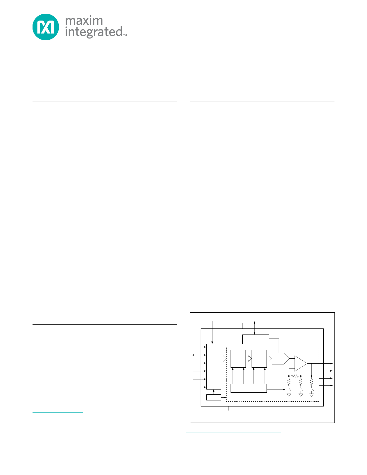
Functional Diagram
VDDIO
VDD REF
SCL
SDA
ADDR0
(ADDR1)
CLR
(LDAC)
I2C SERIAL
INTERFACE
POR
INTERNAL REFERENCE/
EXTERNAL BUFFER
CODE
REGISTER
DAC
LATCH
8 -/10-/12-BIT
DAC
CODE
CLEAR /
RESET
LOAD
CLEAR /
RESET
DAC CONTROL LOGIC
POWER-DOWN
GND
( ) TSSOP PACKAGE ONLY
MAX5813
MAX5814
MAX5815
1 OF 4 DAC CHANNELS
BUFFER
100kI 1kI
OUTA
OUTB
OUTC
OUTD
For related parts and recommended products to use with this part, refer to: www.maximintegrated.com/MAX5813.related
For pricing, delivery, and ordering information, please contact Maxim Direct
at 1-888-629-4642, or visit Maxim’s website at www.maximintegrated.com.
19-6167; Rev 3; 1/13
1 page 
MAX5813/MAX5814/MAX5815
Ultra-Small, Quad-Channel, 8-/10-/12-Bit Buffered
Output DACs with Internal Reference and I2C Interface
ELECTRICAL CHARACTERISTICS (continued)
(VDD = 2.7V to 5.5V, VDDIO = 1.8V to 5.5V, VGND = 0V, CL = 200pF, RL = 2kI, TA = -40NC to +125NC, unless otherwise noted. Typical
values are at TA = +25NC.) (Note 3)
PARAMETER
SYMBOL
CONDITIONS
REFERENCE INPUT
Reference Input Range
Reference Input Current
Reference Input Impedance
REFERENCE OUPUT
VREF
IREF
RREF
VREF = VDD = 5.5V
Reference Output Voltage
Reference Temperature
Coefficient (Note 10)
Reference Drive Capacity
VREF
VREF = 2.048V, TA = +25NC
VREF = 2.5V, TA = +25NC
VREF = 4.096V, TA = +25NC
MAX5815A
MAX5813/MAX5814/MAX5815B
External load
Reference Capacitive Load
Reference Load Regulation
Reference Line Regulation
ISOURCE = 0 to 500FA
POWER REQUIREMENTS
Supply Voltage
VDD
VREF = 4.096V
All other options
I/O Supply Voltage
Supply Current (Note 11)
Interface Supply Current
(Note 11)
VDDIO
IDD
IDDIO
Internal reference
External reference
VREF = 2.048V
VREF = 2.5V
VREF = 4.096V
VREF = 3V
VREF = 5V
All DACs off, internal reference ON
Power-Down Mode Supply
Current
All DACs off, internal reference OFF,
IPD TA = -40NC to +85NC
All DACs off, internal reference OFF,
TA = +125NC
DIGITAL INPUT CHARACTERISTICS (SCL, SDA, ADDR0, ADDR1, LDAC, CLR)
Input High Voltage (Note 11)
2.2V < VDDIO < 5.5V
VIH
1.8V < VDDIO < 2.2V
MIN TYP MAX UNITS
1.24
VDD
55 74
75 100
V
FA
kI
2.043
2.494
4.086
2.048
2.500
4.096
Q3.7
Q10
25
200
2
0.05
2.053
2.506
4.106
Q10
Q25
V
ppm/NC
kI
pF
mV/mA
mV/V
4.5 5.5
2.7 5.5
1.8 5.5
0.93 1.25
0.98 1.30
1.16 1.50
0.85 1.15
1.10 1.40
1
140
0.5 1
1.2 2.5
V
V
mA
FA
FA
0.7 x
VDDIO
0.8 x
VDDIO
V
V
Maxim Integrated
5
5 Page 
MAX5813/MAX5814/MAX5815
Ultra-Small, Quad-Channel, 8-/10-/12-Bit Buffered
Output DACs with Internal Reference and I2C Interface
Typical Operating Characteristics (continued)
(MAX5815, 12-bit performance, TA = +25°C, unless otherwise noted.)
CHANNEL-TO-CHANNEL FEEDTHROUGH
(VDD = 5V, VREF = 4.096V (INTERNAL),
TA = +25NC, NO LOAD) MAX5813 toc25
NO LOAD
NO LOAD
TRANSITIONING DAC
1V/div
STATIC DAC
1.25mV/div
DIGITAL FEEDTHROUGH
(VDD = VREF = 5V, RL = 2kI, CL = 200pF)
MAX5813 toc26
VDD = 5V
VREF = 5V (EXTERNAL)
DACS AT MIDSCALE
VOUT
1.65mV/div
TRANSITIONING DAC: 0 TO FULL SCALE
STATIC DAC: MIDSCALE
ANALOG CROSSTALK = 1.1nV*S
4µs/div
TRIGGER PULSE
10V/div
OUTPUT LOAD REGULATION
10
8 VDD = VREF
6
4 VDD = 5V
2
0 VDD = 3V
-2
-4
-6
-8
-10
-30 -20 -10 0 10 20 30 40 50
IOUT (mA)
60
HEADROOM AT RAILS
vs. OUTPUT CURRENT (VDD = VREF)
5.00
4.50 DAC = FULL SCALE
4.00 VDD = 5V, SOURCING
3.50
3.00
2.50
2.00 VDD = 3V, SOURCING
1.50
1.00
0.50
DAC = ZERO SCALE
0
01234
VDD = 3V AND 5V
SINKING
56789
IOUT (mA)
10
Maxim Integrated
DIGITAL FEEDTHROUGH = 0.1nV·s·
40ns/div
OUTPUT CURRENT LIMITING
500
400 VDD = VREF
300
200
100 VDD = 5V
0
-100 VDD = 3V
-200
-300
-400
-500
-30 -20 -10 0 10 20 30 40 50 60 70
IOUT (mA)
NOISE-VOLTAGE DENSITY
VS. FREQUENCY (DAC AT MIDSCALE)
350
300
VDD = 5V, VREF = 4.096V
(INTERNAL)
250 VDD = 5V, VREF = 2.5V
(INTERNAL)
200 VDD = 5V, VREF = 2.048V
(INTERNAL)
150
100
50 VDD = 5V, VREF = 4.5V
(EXTERNAL)
0
100 1k 10k
FREQUENCY (Hz)
100k
11
11 Page | ||
| Páginas | Total 30 Páginas | |
| PDF Descargar | [ Datasheet MAX5813.PDF ] | |
Hoja de datos destacado
| Número de pieza | Descripción | Fabricantes |
| MAX5811 | 10-Bit / Low-Power / 2-Wire Interface / Serial / Voltage-Output DAC | Maxim Integrated |
| MAX5812 | 12-Bit Low-Power / 2-Wire / Serial Voltage-Output DAC | Maxim Integrated |
| MAX5813 | Ultra-Small Quad-Channel 8-/10-/12-Bit Buffered Output DACs | Maxim Integrated Products |
| MAX5814 | Ultra-Small Quad-Channel 8-/10-/12-Bit Buffered Output DACs | Maxim Integrated Products |
| Número de pieza | Descripción | Fabricantes |
| SLA6805M | High Voltage 3 phase Motor Driver IC. |
Sanken |
| SDC1742 | 12- and 14-Bit Hybrid Synchro / Resolver-to-Digital Converters. |
Analog Devices |
|
DataSheet.es es una pagina web que funciona como un repositorio de manuales o hoja de datos de muchos de los productos más populares, |
| DataSheet.es | 2020 | Privacy Policy | Contacto | Buscar |