|
|
|
PDF SS14 Data sheet ( Hoja de datos )
| Número de pieza | SS14 | |
| Descripción | SURFACE MOUNT SCHOTTKY BARRIER RECTIFIERS | |
| Fabricantes | HY | |
| Logotipo | ||
 1. 40V, SMD Schottky Barrier Rectifier Hay una vista previa y un enlace de descarga de SS14 (archivo pdf) en la parte inferior de esta página. Total 2 Páginas | ||
|
No Preview Available !
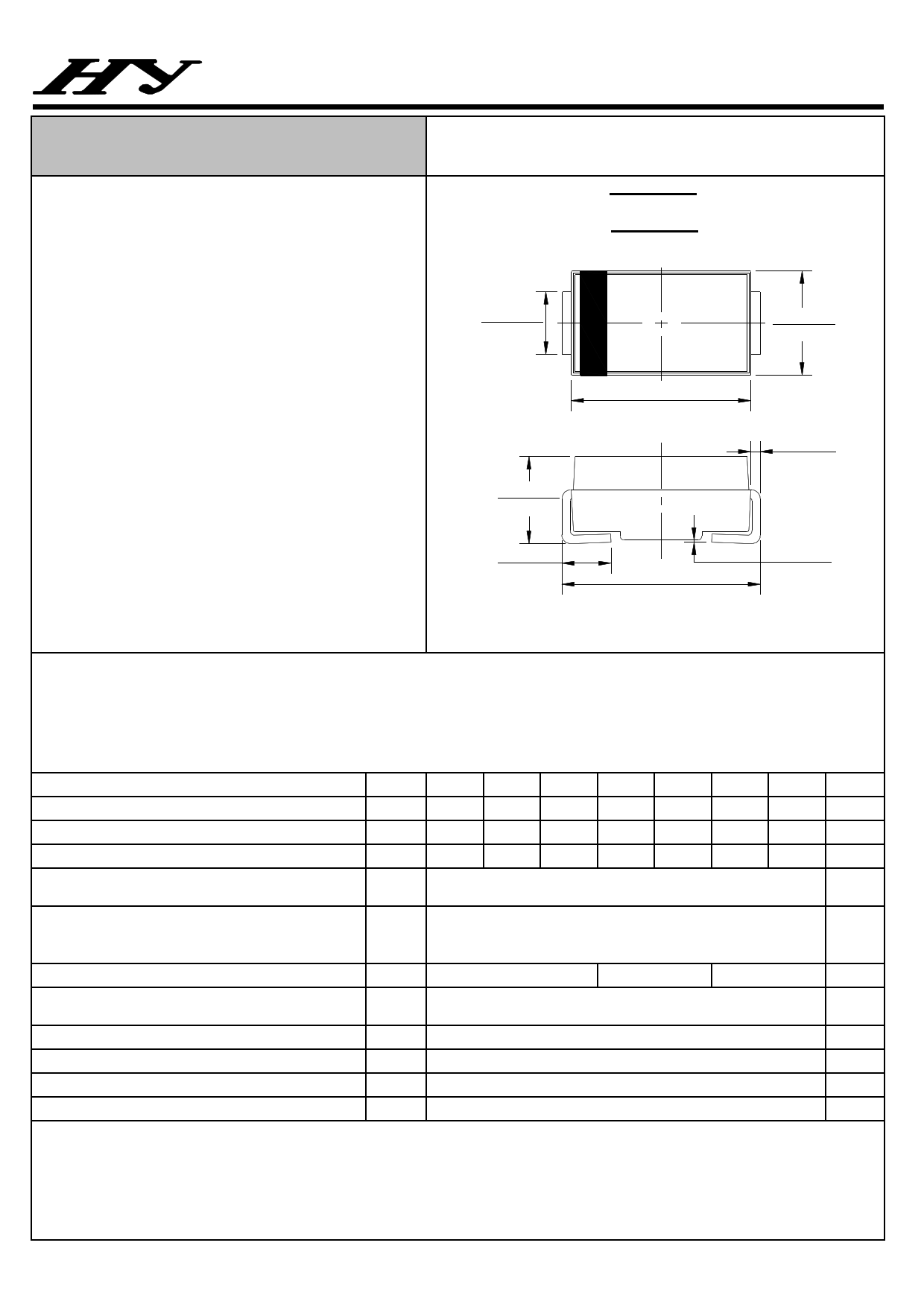
SURFACE MOUNT
SCHOTTKY BARRIER RECTIFIERS
FEATURES
●For surface mounted applications
●Metal-Semiconductor junction with guarding
●Epitaxial construction
●Very low forward voltage drop
●High current capability
●Plastic material has UL flammability
classification 94V-0
●For use in low voltage, high frequency inverters,
free wheeling, and polarity protection applications.
MECHANICAL DATA
●Case: Molded Plastic
●Polarity: lndicated by cathode band
●Weight: 0.002 ounces,0.053 grams
SS12 thru SS110
REVERSE VOLTAGE - 20 to 100 Volts
FORWARD CURRENT - 1.0 Ampere
SMA
.065(1.65)
.049(1.25)
.181(4.60)
.157(4.00)
.103(2.62)
.079(2.00)
.060(1.52)
.030(0.76)
.208(5.28)
.188(4.80)
.114(2.90)
.093(2.35)
.012(.305)
.006(.152)
.008(.203)
.002(.051)
Dimensions in inches and (millimeters)
MAXIMUM RATINGS AND ELECTRICAL CHARACTERISTICS
Rating at 25℃ ambient temperature unless otherwise specified.
Single phase, half wave ,60Hz, resistive or inductive load.
For capacitive load, derate current by 20%
CHARACTERISTICS
SYMBOL
Maximum Recurrent Peak Reverse Voltage
VRRM
Maximum RMS Voltage
VRMS
Maximum DC Blocking Voltage
VDC
Maximum Average Forward
Rectified Current
Peak Forward Surge Current
@TL=100 ℃
8.3ms Single Half Sine-Wave
Super Imposed On Rated Load (JEDEC Method)
I(AV)
IFSM
Maximum Forward Voltage at 1.0A DC
Maximum DC Reverse Current
at Rated DC Blocking Voltage
@TJ=25℃
@TJ=100℃
Typical Junction Capacitance (Note1)
VF
IR
CJ
Typical Thermal Resistance (Note2)
RθJL
Operating Temperature Range
TJ
Storage Temperature Range
TSTG
NOTES:1.Measured at 1.0 MHz and applied reverse voltage of 4.0V DC.
2.Thermal resistance junction to lead.
SS12
20
14
20
SS13
30
21
30
0.55
SS14
40
28
40
SS15
50
35
50
1.0
SS16
60
42
60
30
0.70
1.0
10
110
20
-55 to + 150
-55 to + 150
SS18
80
56
80
SS110
100
70
100
0.85
UNIT
V
V
V
A
A
V
mA
pF
℃/W
℃
℃
~ 204 ~
REV. 1, 30-Dec-2011
1 page | ||
| Páginas | Total 2 Páginas | |
| PDF Descargar | [ Datasheet SS14.PDF ] | |
Hoja de datos destacado
| Número de pieza | Descripción | Fabricantes |
| SS100 | (SS12 - SS100) 1.0 Ampere Schottky Barrier Rectifiers | Fairchild Semiconductor |
| SS100 | (SS12 - SS100) SURFACE MOUNT SCHOTTKY BARRIER RECTIFIERS | Jinan Gude Electronic Device |
| SS100 | (SS12 - SS100) SURFACE MOUNT SCHOTTKY BARRIER RECTIFIER | TRSYS |
| SS100 | Surface Mount Digital Position Sensors | HONEYWELL |
| Número de pieza | Descripción | Fabricantes |
| SLA6805M | High Voltage 3 phase Motor Driver IC. |
Sanken |
| SDC1742 | 12- and 14-Bit Hybrid Synchro / Resolver-to-Digital Converters. |
Analog Devices |
|
DataSheet.es es una pagina web que funciona como un repositorio de manuales o hoja de datos de muchos de los productos más populares, |
| DataSheet.es | 2020 | Privacy Policy | Contacto | Buscar |