|
|
|
PDF G6B-2114P-US Data sheet ( Hoja de datos )
| Número de pieza | G6B-2114P-US | |
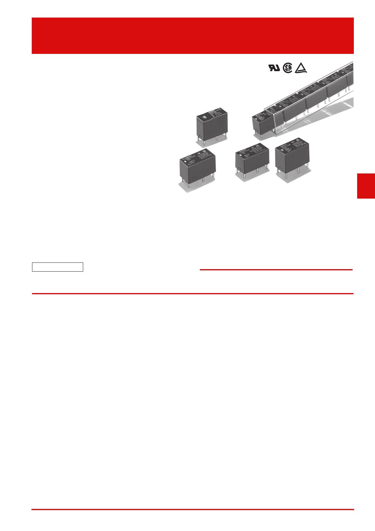
| Descripción | PCB Power Relay | |
| Fabricantes | Omron Electronics | |
| Logotipo | ||
Hay una vista previa y un enlace de descarga de G6B-2114P-US (archivo pdf) en la parte inferior de esta página. Total 10 Páginas | ||
|
No Preview Available !
G6B
PCB Power Relay
High Capacity and High
Dielectric Strength Miniature
Relay with Fully Sealed
Construction in 5 A (8 A)
SPST-NO (1a),
SPST-NC (1b),
DPST-NO (2a),
DPST-NC (2b) Types
• High sensitive with operating power of 98 mW.
(G6B-1114P-US and G6B-1174P-US models)
• High insulation with dielectric strength of 3,000VAC
between coil and contacts (impulse withstand voltage of
6 kV).
• Stick packing models are provided in consideration of compatibility to the automatic production line.
• Standard model conforms to UL/CSA standards. Other SEV approved models are also available.
• AgSnIn contacts suitable for loads that generate surge voltage (inductive load, capacity load, etc.) available. (-FD type)
• Ultrasonic cleanable models available. (-U type)
• Operation indicator & built-in surge absorption diode available. (-ND type)
• 2-Pole type available.
RoHS Compliant
■Application Examples
• Ideal for output applications of control equipments
■Model Number Legend
G6B-@-@@@@@-@-@-@-@-@
— ————— — — — — —
1 2 3 4 5 6 7 8 9 10 11
1. Relay Function
None: Single-side stable
U : Single-winding latching
(G6B@-1114 models only)
K : Double-winding latching
(G6B@-1114 models only)
2. Number of poles
1: 1-pole
2: 2-pole
3. Contact Form
1: SPST-NO (1a)
1: SPST-NO (1a)+SPST-NC (1b)
2: DPST-NO (2a)
0: DPST-NC (2b)
4. Classification
1: Standard
7: High-capacity
5. Enclosure rating
4: Fully sealed
7: Flux protection
6. Terminal Shape
P: PCB terminals
Socket mounting terminals
7. Contact material
None: Standard (Ag-alloy (Cd free))
FD : AgSnIn contact
(Suitable for DC inductive load with
high inrush current)
8. Operation Indicator Diode
Availability
None: Standard
ND : Operation indicator & coil surge
absorption diode
(for -1177 type only)
9. Approved Standards
US: UL/CSA
10. Washability
None: Standard
U : For ultrasonically cleanable
11. Mounting
None: Mounted directly to PCB
P6B : Mounted to Socket
G
6
B
http://www.Datasheet4U.com
1
1 page 
G6B
■Engineering Data
● Maximum Switching Current
G6B-1114P-US
G6B-1174P-FD-US
40
20
10
AC resistive load
5
3
AC
2 inductive
1
DC inductive load
(L/R = 7 ms)
load
cosφ = 0.4
0.5 DC resistive load
0.3
0.2
0.1
03
5 10 20 30
100 300 500
Switching voltage (V)
● Durability
G6B-1114P-US
G6B-1174P-US
G6B-1174P-FD-US
1,000
500
300
100
50
30
G6B-1114P-US
250 VAC/30 VDC resistive load
G6B-1174P-FD-US
250 VAC/30 VDC resistive load
G6B-1174P-US
250 VAC/30 VDC
resistive load
10
Higher
5 G6B-1114P-US
G6B-1174P-FD-US
capacity
3 G6B-1174P-US
250 VAC/30 VDC inductive load
(cosφ = 0.4, L/R = 7 ms)
1
01 2 3 4 5 6 7
8
9 10
Switching current (A)
● Ambient Temperature vs. Must
Operate and Must Release Voltage
G6B-1114P-US
100
Sample:
G6B-1114P-US
Number of Relays: 5 pcs
80
60
Must operate voltage
Must release voltage
max.
X
min.
40 max.
X
min.
20
0
−40 −20
0
20 40 60 80
Ambient temperature (°C)
PCB Power Relay
G6B-1174P-US
100
50
30
AC resistive load
10
8
5
3
2
DC resistive load
1
AC
inductive
load
0.5
DC inductive load
0.3
0.1
03
5 10
30 50 100
380 1,000
Switching voltage (V)
G6B-2114P(-FD)-US
G6B-2214P(-FD)-US
G6B-2014P(-FD)-US
1,000
500
300
G6B-2114P(-FD)-US
G6B-2214P(-FD)-US
G6B-2014P(-FD)-US
250 VAC/30 VDC inductive load
(cosφ = 0.4, L/R = 7 ms)
100
G6B-2114P-US
50 G6B-2214P-US
G6B-2014P-US
30 250 VAC/30 VDC resistive load
10
5 G6B-2114P-FD-US
G6B-2214P-FD-US
3 G6B-2014P-FD-US
250 VAC resistive load
1
0 1 1.5 2 3 4 5 6 7 8 9 10
Switching current (A)
● Mutual Magnetic Interference
G6B-1114P-US
2.54 mm
Sample
De-energized
Sample
Energized
Must operate voltage
Must release voltage
Initial stage
+1.0
Test
+0.5
0
−0.5
−1.0 Average value
Initial stage
+1.0
Test
+0.5
0
−0.5
−1.0 Average value
G6B-2114P-US
G6B-2214P-US
G6B-2014P-US
100
50
30
G6B-2114P-FD-US
G6B-2214P-FD-US
G6B-2014P-FD-US
10
5
AC inductive load
(cosφ = 0.4)
AC resistive
load
3
2
1.5
1
0.5
0.3
0.1
0
DC resistive load
AC
resistive
load
DC inductive load
(L/R = 7 ms)
3 5 10
30 50 100
300 500 1,000
Switching voltage (V)
● Ambient Temperature vs.
Maximum Coil Voltage
G6B-1114P-US
G6B-2114P-US
G6B-1174P-US
G6B-2214P-US
G6B-1174P-FD-US G6B-2014P-US
200 G
6
180 G6B-1114P-US
B
G6B-1174P-US
G6B-1174P-FD-US
160
140
130
120
110
100 G6B-2114P-US
G6B-2214P-US
G6B-2014P-US
80
60
0 20 23 30 40 50 60 70 80 90
Ambient temperature (°C)
Note: The maximum coil voltage refers to the
maxi-mum value in a varying range of
operating power voltage, not a continuous
voltage.
G6B-1114P-US
2.54 mm
Sample
De-energized
Sample
Energized
Must operate voltage
Must release voltage
Initial stage
+1.0
Test
+0.5
0
−0.5
−1.0 Average value
Initial stage
+1.0
Test
+0.5
0
−0.5
−1.0 Average value
5
5 Page | ||
| Páginas | Total 10 Páginas | |
| PDF Descargar | [ Datasheet G6B-2114P-US.PDF ] | |
Hoja de datos destacado
| Número de pieza | Descripción | Fabricantes |
| G6B-2114P-US | PCB Power Relay | Omron Electronics |
| G6B-2114P-US-U | PCB Power Relay | Omron Electronics |
| Número de pieza | Descripción | Fabricantes |
| SLA6805M | High Voltage 3 phase Motor Driver IC. |
Sanken |
| SDC1742 | 12- and 14-Bit Hybrid Synchro / Resolver-to-Digital Converters. |
Analog Devices |
|
DataSheet.es es una pagina web que funciona como un repositorio de manuales o hoja de datos de muchos de los productos más populares, |
| DataSheet.es | 2020 | Privacy Policy | Contacto | Buscar |