|
|
|
PDF EE-SX67 Data sheet ( Hoja de datos )
| Número de pieza | EE-SX67 | |
| Descripción | Photomicrosensor | |
| Fabricantes | OMRON | |
| Logotipo | ||
Hay una vista previa y un enlace de descarga de EE-SX67 (archivo pdf) en la parte inferior de esta página. Total 9 Páginas | ||
|
No Preview Available !
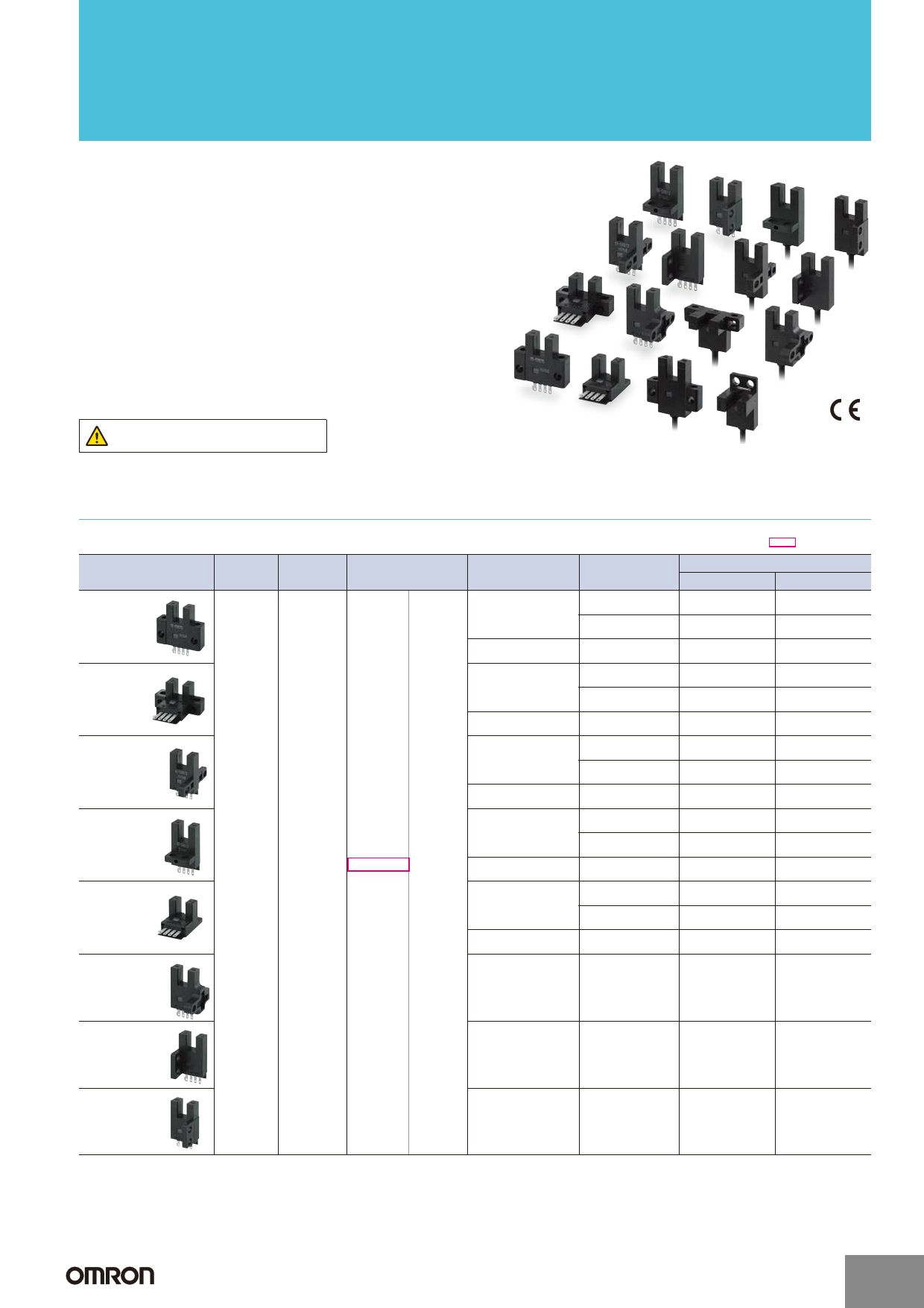
Slot-type Photomicrosensor (Non-modulated) *1
EE-SX47/67
Photomicrosensor with 50- to 100-mA direct
switching capacity for built-in application.
■ Series includes models that enable switching between
dark-ON and light-ON operation.
■ Response frequency as high as 1 kHz.
■ Easy operation monitoring with bright light indicator.
■ Wide operating voltage range: 5 to 24 VDC
■ Models in which the light indicator turns ON for dark-ON
operation are also available.
■ A wide range of variations in eight different shapes.
■ Flexible robot cable is provided as a standard feature. *2
Be sure to read Safety Precautions on
page 5.
*1. Pre-wired Models are available only in the EE-SX67 Series.
*2. Only for Pre-wired Models.
Ordering Information
Connector
Appearance
Standard
L-shaped
T-shaped,
slot center
7 mm
Close-
mounting
Close-
mounting
T-shaped,
slot center
10 mm
Sensing
method
Connect-
ing method
Sensing distance
Output
configuration
Indicator mode
Dark-ON/Light-ON Incident light
(selectable) *3
No incident light
Light-ON
Incident light
Dark-ON/Light-ON Incident light
(selectable) *3
No incident light
Light-ON
Incident light
Dark-ON/Light-ON Incident light
(selectable) *3
No incident light
Light-ON
Incident light
Through-
beam
type
(with slot)
Connector
(4 poles)
Dark-ON/Light-ON Incident light
(selectable) *3
No incident light
5 mm Light-ON
Incident light
(slot width)
Dark-ON/Light-ON Incident light
(selectable) *3
No incident light
Light-ON
Incident light
Infrared light
Model
NPN output PNP output
EE-SX670
EE-SX670P
EE-SX670A EE-SX670R
EE-SX470
EE-SX470P
EE-SX671
EE-SX671P
EE-SX671A EE-SX671R
EE-SX471
EE-SX471P
EE-SX672
EE-SX672P
EE-SX672A EE-SX672R
EE-SX472
EE-SX472P
EE-SX673
EE-SX673P
EE-SX673A EE-SX673R
EE-SX473
EE-SX473P
EE-SX674
EE-SX674P
EE-SX674A EE-SX674R
EE-SX474
EE-SX474P
Dark-ON/Light-ON
(selectable) *3
Incident light
EE-SX675
EE-SX675P
F-shaped
Dark-ON/Light-ON
(selectable) *3
Incident light
EE-SX676
EE-SX676P
R-shaped
Dark-ON/Light-ON
(selectable) *3
Incident light
EE-SX677
EE-SX677P
*3. Dark-ON when the L terminal of the connector is opened, and light-ON when the L terminal and positive (+) terminal are short-circuited. When used at light-ON, it
is useful to select the connector EE-1001-1. The L terminal and positive (+) terminal of this connector are short-circuited in advance.
http://www.Datasheet4U.com
1
1 page 
EE-SX47/67
PNP Output
Model
Output
configuration
Timing charts
Light-ON
EE-SX67@P
EE-SX67@P-WR
EE-SX67@P-CJ1-R
Dark-ON
Incident
Interrupted
Light indicator ON
(red)
OFF
Output
transistor
ON
OFF
Load
(relay)
Operates
Releases
Incident
Interrupted
Light indicator ON
(red)
OFF
Output
transistor
ON
OFF
Load
(relay)
Operates
Releases
EE-SX670R
EE-SX671R
EE-SX672R
EE-SX673R
EE-SX674R
Light-ON
Dark-ON
Incident
Interrupted
Light indicator ON
(red)
OFF
Output
transistor
ON
OFF
Load
Operates
(e.g., relay) Releases
Incident
Interrupted
Light indicator ON
(red)
OFF
Output
transistor
ON
OFF
Load
Operates
(e.g., relay) Releases
EE-SX470P
EE-SX471P
EE-SX472P
EE-SX473P
EE-SX474P
Light-ON
Incident
Interrupted
Light indicator ON
(red)
OFF
Output
transistor
ON
OFF
Load
(relay)
Operates
Releases
Terminal
connections
Short-circuited
between
L terminal and
positive terminal
Output circuit
Open between
L terminal and
positive terminal
Light indicator
(red)
*
L
Short-circuited
between
L terminal and
positive terminal
Main
circuit
OUT
IC
Load
*The terminal arrangement depends on the model.
Check the demensional diagrams.
5 to
24 VDC
Open between
L terminal and
positive terminal
Light indicator (red)
---
Main
OUT
5 to
24 VDC
circuit
IC
Load
Safety Precautions
Refer to Warranty and Limitations of Liability.
WARNING
This product is not designed or rated for ensuring
safety of persons either directly or indirectly.
Do not use it for such purposes.
Precautions for Safe Use
● Operating Environment
These Photomicrosensors have an IP50 (conforms to IEC) enclosure
and do not have a water-proof or dust-proof structure. Therefore, do
not use them in applications in which the sensor will be subjected to
splashes from water, oil, or any other liquid. Liquid entering the
Sensor may result in malfunction.
Precautions for Correct Use
Make sure that this product is used within the rated ambient environment conditions.
● Installation
• When direct soldering to the terminals, use the following guidelines.
Soldering Conditions
Item
Soldering
iron
Temper-
ature
350°C
max.
Permissible
time
3s
max.
Remarks
The portion between the base of
the terminals and the position
1.5 mm from the terminal base
must not be soldered.
• The terminal base uses a polycarbonate resin, which could be deformed by
excessive soldering heat, resulting in damage to the product's functionality.
● Lot Number and Model Number Legend
In the following diagrams, X43M
indicates the lot number and factory
where the product was
manufactured. Do not include this
code with the model number when
ordering.
EE-SX@70@
EE-SX670
X43M
Model number
Lot number and factory code
5
5 Page | ||
| Páginas | Total 9 Páginas | |
| PDF Descargar | [ Datasheet EE-SX67.PDF ] | |
Hoja de datos destacado
| Número de pieza | Descripción | Fabricantes |
| EE-SX67 | Photomicrosensor | OMRON |
| EE-SX67 | (EE-SX47 / EE-SX67) Photomicrosensor | OMRON |
| EE-SX67x | (EE-SX47 / EE-SX67) Photomicrosensor | OMRON |
| Número de pieza | Descripción | Fabricantes |
| SLA6805M | High Voltage 3 phase Motor Driver IC. |
Sanken |
| SDC1742 | 12- and 14-Bit Hybrid Synchro / Resolver-to-Digital Converters. |
Analog Devices |
|
DataSheet.es es una pagina web que funciona como un repositorio de manuales o hoja de datos de muchos de los productos más populares, |
| DataSheet.es | 2020 | Privacy Policy | Contacto | Buscar |