|
|
|
PDF HI-390 Data sheet ( Hoja de datos )
| Número de pieza | HI-390 | |
| Descripción | CMOS Analog Switch | |
| Fabricantes | Intersil Corporation | |
| Logotipo | ||
Hay una vista previa y un enlace de descarga de HI-390 (archivo pdf) en la parte inferior de esta página. Total 7 Páginas | ||
|
No Preview Available !
Data Sheet
HI-390
July 1999
File Number 4754
CMOS Analog Switch
The Hl-390 switch is a monolithic device fabricated using
CMOS technology and the Intersil dielectric isolation process.
This device is TTL compatible and features low leakage and
supply currents, low and nearly constant ON resistance over
the analog signal range, break-before-make switching and
low power dissipation.
Ordering Information
PART
NUMBER
TEMP. RANGE
(oC)
PACKAGE
HI1-0390-2
HI3-0390-5
-55 to 125
0 to 75
16 Ld CERDIP
16 Ld PDIP
PKG. NO.
F16.3
E16.3
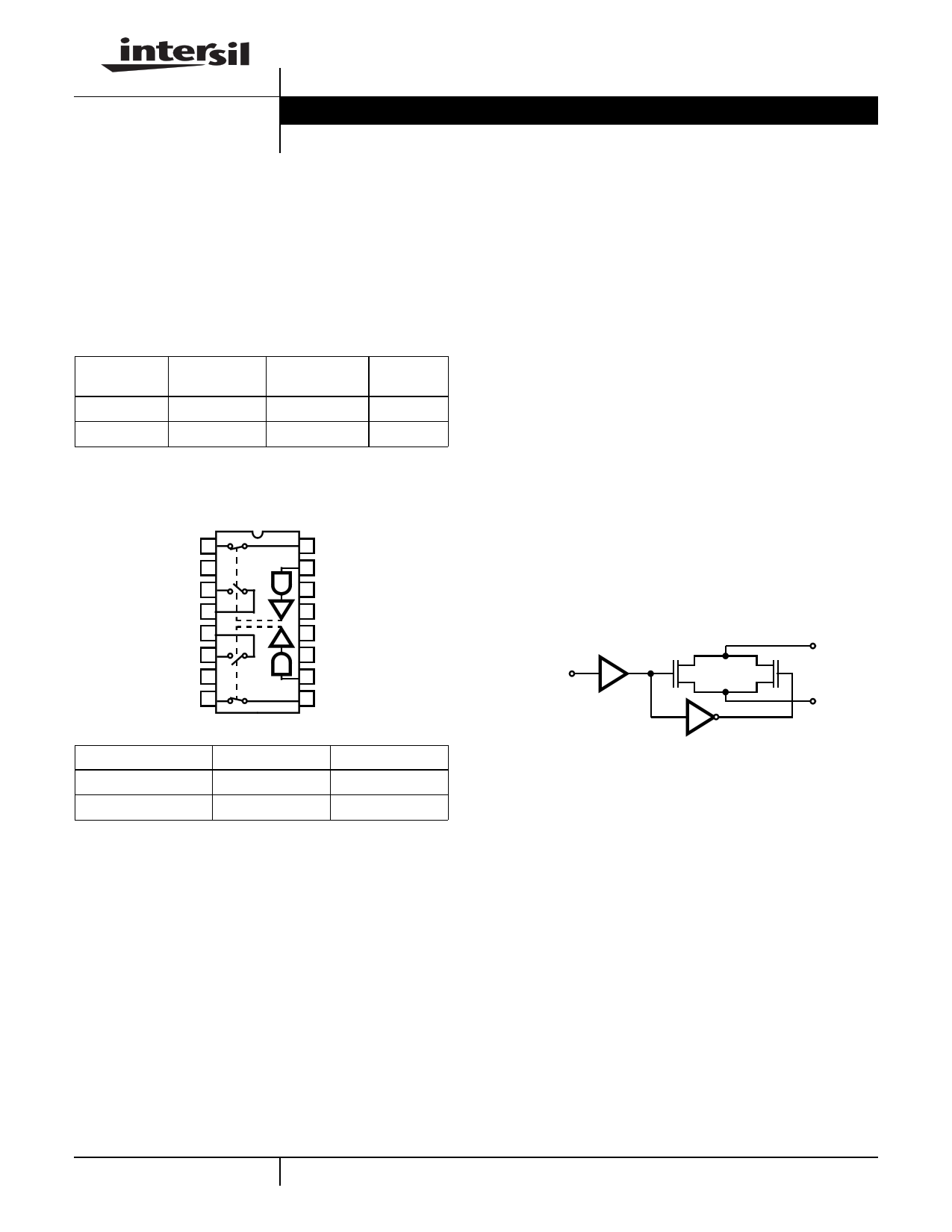
Pinout Switch States shown for a Logic “1” Input
DUAL SPDT HI-390 (CERDIP, PDIP)
TOP VIEW
D1 1
NC 2
D3 3
S3 4
S4 5
D4 6
NC 7
D2 8
16 S1
15 IN1
14 V-
13 GND
12 NC
11 V+
10 IN2
9 S2
LOGIC
0
1
SW1, SW2
OFF
ON
SW3, SW4
ON
OFF
Features
• Analog Signal Range (±15V Supplies) . . . . . . . . . . . ±15V
• Low Leakage . . . . . . . . . . . . . . . . . . . . . . . . . . . . . . 40pA
• Low On Resistance . . . . . . . . . . . . . . . . . . . . . . . . . . 35Ω
• Break-Before-Make Delay . . . . . . . . . . . . . . . . . . . . 60ns
• Charge Injection . . . . . . . . . . . . . . . . . . . . . . . . . . . . 30pC
• TTL Compatible
• Symmetrical Switch Elements
• Low Operating Power . . . . . . . . . . . . . . . . . . . . . . . 1.0mW
Applications
• Sample and Hold (i.e., Low Leakage Switching)
• Op Amp Gain Switching (i.e., Low On Resistance)
• Portable, Battery Operated Circuits
• Low Level Switching Circuits
• Dual or Single Supply Systems
Functional Diagram
S
IN N P
D
1 CAUTION: These devices are sensitive to electrostatic discharge; follow proper IC Handling Procedures.
http://www.intersil.com or 407-727-9207 | Copyright © Intersil Corporation 1999
1 page 
Test Circuits and Waveforms (Continued)
HI-390
5
0
-5 VGEN = 0V
0 0.4 0.8 1.2
TIME (µs)
FIGURE 1E. VANALOG = 0V
1.6
0
-5
VGEN = -5V
0 0.4 0.8 1.2
TIME (µs)
FIGURE 1F. VANALOG = -5V
1.6
0
-5
-10
VGEN = -10V
0 0.4 0.8 1.2 1.6
TIME (µs)
NOTE:
FIGURE 1G. VANALOG = -10V
10. If RGEN, RL or CL is increased, there will be proportional increases in rise and/or fall RC times.
FIGURE 1. SWITCHING WAVEFORMS FOR VARIOUS ANALOG INPUT VOLTAGES
Typical Performance Curves
80
V+ = +15V, V- = -15V
60
40
20
125oC
25oC
-55oC
0
-15 -10
-5 0
5
DRAIN VOLTAGE (V)
10
FIGURE 2. rDS(ON) vs VD
15
80
TA = 25oC
60
D
C
40 B
A
20 A V+ = +15V, V- = -15V
B V+ = +10V, V- = -10V
C V+ = +7.5V, V- = -7.5V
D V+ = +5V, V- = -5V
0
-15 -10
-5
0
5
DRAIN VOLTAGE (V)
10 15
FIGURE 3. rDS(ON) vs VD
5
5 Page | ||
| Páginas | Total 7 Páginas | |
| PDF Descargar | [ Datasheet HI-390.PDF ] | |
Hoja de datos destacado
| Número de pieza | Descripción | Fabricantes |
| HI-390 | CMOS Analog Switch | Intersil Corporation |
| Número de pieza | Descripción | Fabricantes |
| SLA6805M | High Voltage 3 phase Motor Driver IC. |
Sanken |
| SDC1742 | 12- and 14-Bit Hybrid Synchro / Resolver-to-Digital Converters. |
Analog Devices |
|
DataSheet.es es una pagina web que funciona como un repositorio de manuales o hoja de datos de muchos de los productos más populares, |
| DataSheet.es | 2020 | Privacy Policy | Contacto | Buscar |