|
|
|
PDF AN605 Data sheet ( Hoja de datos )
| Número de pieza | AN605 | |
| Descripción | Power MOSFET ( Transistor ) | |
| Fabricantes | Vishay | |
| Logotipo | ||
Hay una vista previa y un enlace de descarga de AN605 (archivo pdf) en la parte inferior de esta página. Total 4 Páginas | ||
|
No Preview Available !
AN605
Vishay Siliconix
Power MOSFET Basics:
Understanding MOSFET Characteristics Associated
With The Figure of Merit
Jess Brown, Guy Moxey
INTRODUCTION
Power MOSFETs have become the standard choice as the
main switching device for low-voltage (<200 V) switchmode
power-supply (SMPS) converter applications. However using
manufacturers’ datasheets to choose or size the correct
device for a specific circuit topology is becoming increasingly
difficult. The main criteria for MOSFET selection are the power
loss associated with the MOSFET (related to the overall
efficiency of the SMPS) and the power-dissipation capability
of the MOSFET (related to the maximum junction temperature
and thermal performance of the package). This application
note focuses on the basic characteristics and understanding
of the MOSFET.
There are several factors which affect the gate of the
MOSFET, and it is necessary to understand the fundamental
basis of the device structure before the MOSFET behavior can
be explained. This application note details the basic structure
of the Trench MOSFET structure, identifying the parasitic
components and defining related terminology. It also
describes how and why the parasitic parameters occur.
With a large variety of topologies, switching speeds, load
currents, and output voltages available, it has become
impossible to identify a generic MOSFET that offers the best
performance across the wide range of circuit conditions. In
some circumstances the on-resistance (rDS(on)) losses
dominate, and in others it is the switching losses of the
transient current and voltage waveforms, or the losses
associated with driving the gate of the device. It also has been
shown1,2 that the input and output capacitances can be the
dominant loss.
INTRODUCING THE FIGURE OF MERIT FOR
MOSFET SELECTION
To add to this confusion, device manufacturers specify
MOSFET parameters at different static and dynamic
conditions, diminishing designers’ ability to compare like for
like. Therefore, the only true method of making the correct
MOSFET choice is to compare a selection of devices within
the circuit in which the MOSFET will be used.
There are methods available that, though sometimes difficult
to implement, enable the designer to compare MOSFETs that
appear suited for a given application. One method for
evaluating MOSFETs is according to “figure of merit.” In its
simplest form, the figure of merit compares gate charge (Qg)
against rDS(on). The result of this multiplication relates to a
certain device technology, which is effectively scalable to
Document Number: 71933
08-Sep-03
achieve the required rDS(on) or Qg . However, the lower the
rDS(on) the higher the gate charge will be. A similar method for
comparing devices is the “Baliga high-frequency figure of
merit,” BHFFOM1, which assumes that the dominant
switching loss will be associated with the charging and
discharging of the input capacitance (Ciss). A third method
uses the “new high-frequency figure of merit,” NHFFOM2,
which assumes that the dominant switching loss is due to the
charging and discharging of the output capacitance (Coss).
The latter two methods are geared towards the applications in
which the MOSFETs will be implemented. However, these
methods only allow like-for-like comparisons; they do not
enable the user to determine that a device with one figure of
merit is necessarily better than a different device with another.
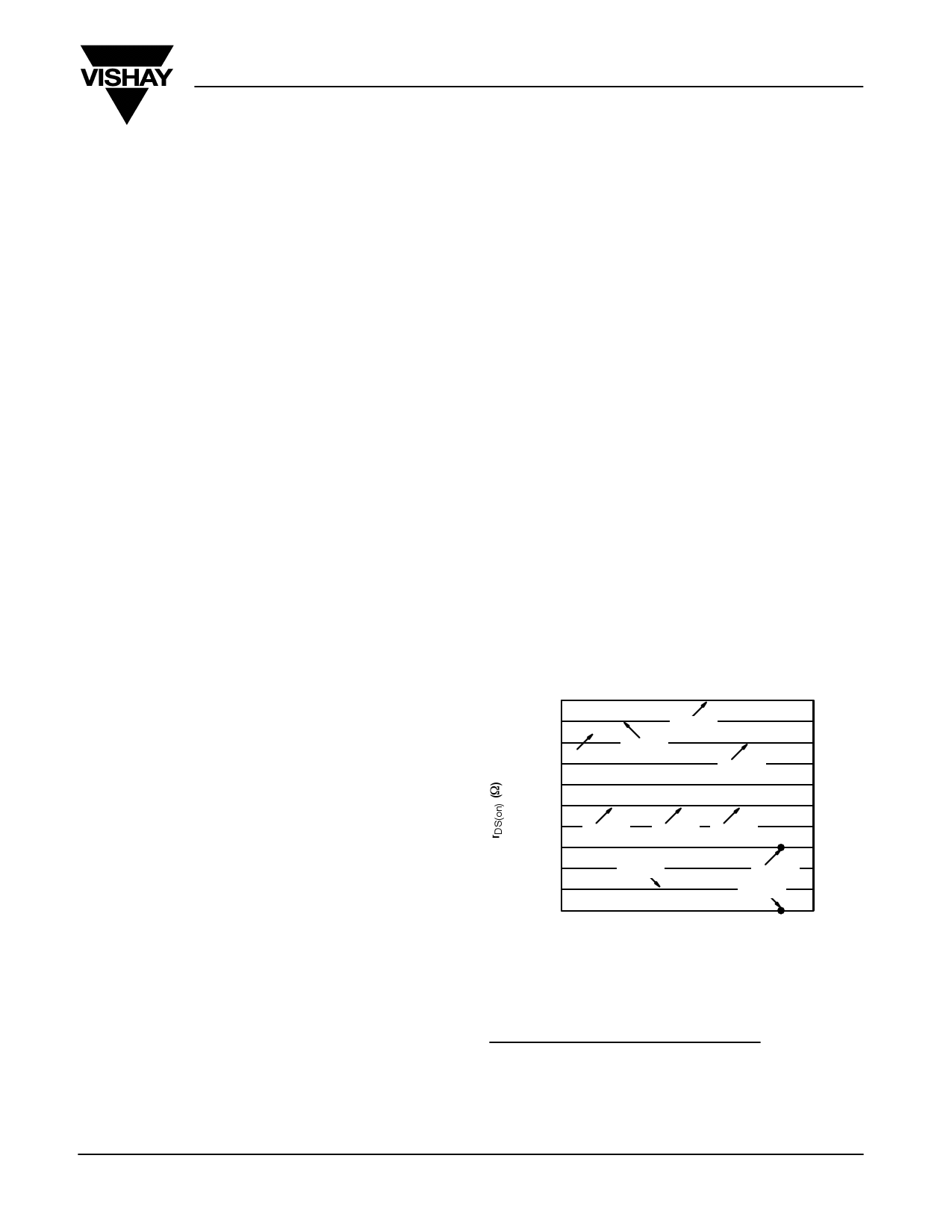
Figure 1 shows the Qg x rDS(on) figure of merit for a sample of
Vishay Siliconix’s range of 30-V SO-8 n-channel MOSFETs.
The Si4888DY, for example, may be better in certain switching
applications than the Si4842DY, but it is not possible to use this
graph—or other graphs using more complex figures of
merit—to determine objectively the best device for a specific
application.
0.015
0.014
0.013
0.012
0.011
Si4886
Si4822
Si4880
Si4420
0.010
0.009
0.008
Si4888
Si4872 Si4874
0.005
0.006
Si4842
Si4430
Si4442
0.007
10
15 20 25 30
Gate Charge (nC)
S Siliconix VGS = 4.5 V
35
40
FIGURE 1. Typical figure of merit for Vishay Siliconix n-channel,
30-V SO-8 MOSFETs
1. IEEE Electron Device Letters, Vol. 10, No. 10, October 1989, “Power
Semiconductor Device Figure of Merit for High Frequency applications,”
B. Jayant Baliga.
2. Proc. of 1995 Int. Sym. on Power Semiconductor Devices and ICs,
Hokohama, “New Power Device Figure of Merit for High-Frequency
Applications,” IL-Jung Kim, Satoshi Mastumoto, Tatsuo Sakai, and
Toshiaka Yachi.
www.vishay.com
1
Free Datasheet http://www.datasheet4u.net/
1 page | ||
| Páginas | Total 4 Páginas | |
| PDF Descargar | [ Datasheet AN605.PDF ] | |
Hoja de datos destacado
| Número de pieza | Descripción | Fabricantes |
| AN601 | Unclamped Inductive Switching Rugged MOSFETs | Vishay Siliconix |
| AN6012 | High Efficiency PWM Step-Down DC/DC Converter | ANT |
| AN602 | Driver ICs | Vishay Siliconix |
| AN603 | Operating ICON H-Bridges in Parallel | Solutions Cubed |
| Número de pieza | Descripción | Fabricantes |
| SLA6805M | High Voltage 3 phase Motor Driver IC. |
Sanken |
| SDC1742 | 12- and 14-Bit Hybrid Synchro / Resolver-to-Digital Converters. |
Analog Devices |
|
DataSheet.es es una pagina web que funciona como un repositorio de manuales o hoja de datos de muchos de los productos más populares, |
| DataSheet.es | 2020 | Privacy Policy | Contacto | Buscar |