|
|
|
PDF AD8178 Data sheet ( Hoja de datos )
| Número de pieza | AD8178 | |
| Descripción | Triple 16 x 5 Video Crosspoint Switch | |
| Fabricantes | Analog Devices | |
| Logotipo | ||
1. AD8178 Hay una vista previa y un enlace de descarga de AD8178 (archivo pdf) en la parte inferior de esta página. Total 30 Páginas | ||
|
No Preview Available !
Data Sheet
FEATURES
Large, triple 16 × 5 high speed, nonblocking switch array
Pin compatible with the AD8175 and AD8176 (16 × 9 switch
arrays) and the AD8177 (16 × 5 switch array)
Differential or single-ended operation
Supports sync-on common-mode and sync-on color
operating modes
RGB and HV outputs available for driving monitor directly
G = +4 operation (differential input to differential output)
Flexible power supplies: +5 V or ±2.5 V
Logic ground for convenient control interface
Serial or parallel programming of switch array
High impedance output disable allows connection of
multiple devices with minimal loading on output bus
Adjustable output CM and black level through external pins
Excellent ac performance
Bandwidth: 450 MHz
Slew rate: 1650 V/μs
Settling time: 4 ns to 1% to support 1600 × 1200 at 85 Hz
Low power of 2.3 W
Low all hostile crosstalk
−82 dB at 5 MHz
−47 dB at 500 MHz
Wide input common-mode range of 4 V
Reset pin allows disabling of all outputs
Fully populated 26 × 26 ball PBGA package (27 mm × 27 mm,
1 mm ball pitch)
Convenient grouping of RGB signals for easy routing
APPLICATIONS
RGB video switching
KVM
Professional video
GENERAL DESCRIPTION
The AD8178 is a high speed, triple 16 × 5 video crosspoint switch
matrix. It supports 1600 × 1200 RGB displays at 85 Hz refresh rate,
by offering a 450 MHz bandwidth and a slew rate of 1650 V/μs.
With −82 dB of crosstalk and −84 dB isolation (at 5 MHz), the
AD8178 is useful in many high speed video applications.
The AD8178 supports two modes of operation: differential-in to
differential-out mode with sync-on CM signaling passed
through the switch and differential-in to differential-out mode
with CM signaling removed through the switch. The output CM
and black level can be conveniently set via external pins.
Rev. A
Document Feedback
Information furnished by Analog Devices is believed to be accurate and reliable. However, no
responsibility is assumed by Analog Devices for its use, nor for any infringements of patents or other
rights of third parties that may result from its use. Specifications subject to change without notice. No
license is granted by implication or otherwise under any patent or patent rights of Analog Devices.
Trademarksandregisteredtrademarksarethepropertyoftheirrespectiveowners.
450 MHz, Triple 16 × 5
Video Crosspoint Switch
AD8178
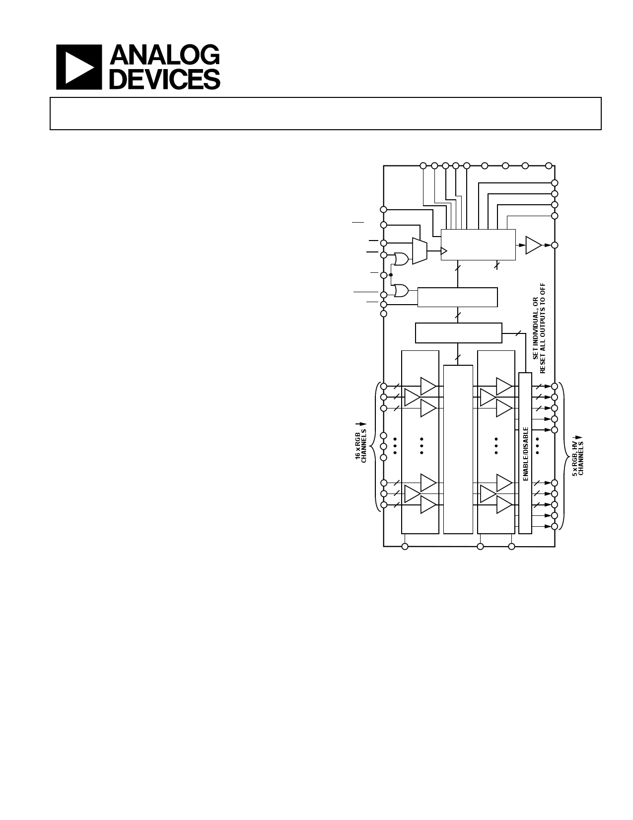
FUNCTIONAL BLOCK DIAGRAM
D0 D1 D2 D3 D4 VPOS VNEG VDD DGND
AD8178
SERIN
SER/PAR
WE
CLK
CS
UPDATE
RST
CMENC
45-BIT SHIFT
1
REGISTER WITH
5-BIT PARALLEL
0 LOADING
25 20
NO
CONNECT
PARALLEL LATCH
25
DECODE
5 × 5:16 DECODERS
5
A0
A1
A2
CLR
SEROUT
INPUT
RECEIVER
G = +2
R2
G2
B2
80 OUTPUT
BUFFER
G = +1
2
2
2
SWITCH
MATRIX
G = +2
R
G
B
H
V
R2
G2
B2
2R
2G
2B
H
V
VBLK
VOCM_CMENCON
Figure 1.
VOCM_CMENCOFF
The outputs can be used single-ended in conjunction with
decoded H and V outputs to drive a monitor directly.
The independent output buffers of the AD8178 can be placed
into a high impedance state to create larger arrays by paralleling
crosspoint outputs. Inputs can be paralleled as well. The AD8178
offers both serial and a parallel programming modes.
The AD8178 is packaged in a fully populated 26 × 26 ball PBGA
package and is available over the extended industrial
temperature range of −40°C to +85°C.
One Technology Way, P.O. Box 9106, Norwood, MA 02062-9106, U.S.A.
Tel: 781.329.4700 ©2007–2016 Analog Devices, Inc. All rights reserved.
Technical Support
www.analog.com
1 page 
AD8178
Parameter
SWITCHING CHARACTERISTICS
Enable On Time
Switching Time, 2 V Step
POWER SUPPLIES
Supply Current
Supply Voltage Range
PSR
OPERATING TEMPERATURE RANGE
Temperature Range
θJA
Test Conditions/Comments
50% UPDATE to 50% output
50% UPDATE to 50% output
VPOS, outputs enabled, no load
Outputs disabled
VNEG, outputs enabled, no load
Outputs disabled
DVDD, outputs enabled, no load
ΔVOUT, DM/ΔVPOS, ΔVPOS = ±0.5 V
ΔVOUT, DM/ΔVNEG, ΔVNEG = ±0.5 V
Operating (still air)
Operating (still air)
Data Sheet
Min Typ Max Unit
80 ns
70 ns
460
290
460
290
4
4.5 to 5.5
−55
−55
mA
mA
mA
mA
mA
V
dB
dB
−40 to +85
15
°C
°C/W
Rev. A | Page 4 of 37
5 Page 
AD8178
Data Sheet
Table 14. Pin Function Description
Pin No. Mnemonic Description
A1 VNEG
Negative Analog Power Supply.
A2 VNEG
Negative Analog Power Supply.
A3 VNEG
Negative Analog Power Supply.
A4 INB12
Input Number 12, Negative Phase.
A5 IPR12
Input Number 12, Positive Phase.
A6 VPOS
Positive Analog Power Supply.
A7 INB11
Input Number 11, Negative Phase.
A8 IPR11
Input Number 11, Positive Phase.
A9 VNEG
Negative Analog Power Supply.
A10 INB10
Input Number 10, Negative Phase.
A11 IPR10
Input Number 10, Positive Phase.
A12 VPOS
Positive Analog Power Supply.
A13 INB9
Input Number 9, Negative Phase.
A14 IPR9
Input Number 9, Positive Phase.
A15 VNEG
Negative Analog Power Supply.
A16 INB8
Input Number 8, Negative Phase.
A17 IPR8
Input Number 8, Positive Phase.
A18 VPOS
Positive Analog Power Supply.
A19 ONB4
Output Number 4, Negative Phase.
A20 OPR4
Output Number 4, Positive Phase.
A21 VNEG
Negative Analog Power Supply.
A22 NC
No Connect.
A23 NC
No Connect.
A24 VNEG
Negative Analog Power Supply.
A25 VNEG
Negative Analog Power Supply.
A26 VNEG
Negative Analog Power Supply.
B1 VNEG
Negative Analog Power Supply.
B2 VNEG
Negative Analog Power Supply.
B3 VNEG
Negative Analog Power Supply.
B4 IPB12
Input Number 12, Positive Phase.
B5 INR12
Input Number 12, Negative Phase.
B6 VPOS
Positive Analog Power Supply.
B7 IPB11
Input Number 11, Positive Phase.
B8 INR11
Input Number 11, Negative Phase.
B9 VNEG
Negative Analog Power Supply.
B10 IPB10
Input Number 10, Positive Phase.
B11 INR10
Input Number 10, Negative Phase.
B12 VPOS
Positive Analog Power Supply.
B13 IPB9
Input Number 9, Positive Phase.
B14 INR9
Input Number 9, Negative Phase.
B15 VNEG
Negative Analog Power Supply.
B16 IPB8
Input Number 8, Positive Phase.
B17 INR8
Input Number 8, Negative Phase.
B18 VPOS
Positive Analog Power Supply.
B19 OPB4
Output Number 4, Positive Phase.
B20 ONR4
Output Number 4, Negative Phase.
B21 VNEG
Negative Analog Power Supply.
B22 NC
No Connect.
B23 NC
No Connect.
B24 VNEG
Negative Analog Power Supply.
B25 VNEG
Negative Analog Power Supply.
Pin No.
B26
C1
C2
C3
C4
C5
C6
C7
C8
C9
C10
C11
C12
C13
C14
C15
C16
C17
C18
C19
C20
C21
C22
C23
C24
C25
C26
D1
D2
D3
D4
D5
D6
D7
D8
D9
D10
D11
D12
D13
D14
D15
D16
D17
D18
D19
D20
D21
D22
D23
D24
Mnemonic
VNEG
VNEG
VNEG
VNEG
ING12
IPG12
VPOS
ING11
IPG11
VNEG
ING10
IPG10
VPOS
ING9
IPG9
VNEG
ING8
IPG8
VPOS
ONG4
OPG4
VNEG
NC
NC
VNEG
VNEG
VNEG
IPR13
INR13
IPG13
VPOS
VPOS
VPOS
VPOS
VPOS
VPOS
VPOS
VPOS
VPOS
VPOS
VPOS
VPOS
VPOS
VPOS
VPOS
V4
H4
VPOS
NC
NC
VNEG
Description
Negative Analog Power Supply.
Negative Analog Power Supply.
Negative Analog Power Supply.
Negative Analog Power Supply.
Input Number 12, Negative Phase.
Input Number 12, Positive Phase.
Positive Analog Power Supply.
Input Number 11, Negative Phase.
Input Number 11, Positive Phase.
Negative Analog Power Supply.
Input Number 10, Negative Phase.
Input Number 10, Positive Phase.
Positive Analog Power Supply.
Input Number 9, Negative Phase.
Input Number 9, Positive Phase.
Negative Analog Power Supply.
Input Number 8, Negative Phase.
Input Number 8, Positive Phase.
Positive Analog Power Supply.
Output Number 4, Negative Phase.
Output Number 4, Positive Phase.
Negative Analog Power Supply.
No Connect.
No Connect.
Negative Analog Power Supply.
Negative Analog Power Supply.
Negative Analog Power Supply.
Input Number 13, Positive Phase.
Input Number 13, Negative Phase.
Input Number 13, Positive Phase.
Positive Analog Power Supply.
Positive Analog Power Supply.
Positive Analog Power Supply.
Positive Analog Power Supply.
Positive Analog Power Supply.
Positive Analog Power Supply.
Positive Analog Power Supply.
Positive Analog Power Supply.
Positive Analog Power Supply.
Positive Analog Power Supply.
Positive Analog Power Supply.
Positive Analog Power Supply.
Positive Analog Power Supply.
Positive Analog Power Supply.
Positive Analog Power Supply.
Output Number 4, V Sync.
Output Number 4, H Sync.
Positive Analog Power Supply.
No Connect.
No Connect.
Negative Analog Power Supply.
Rev. A | Page 10 of 37
11 Page | ||
| Páginas | Total 30 Páginas | |
| PDF Descargar | [ Datasheet AD8178.PDF ] | |
Hoja de datos destacado
| Número de pieza | Descripción | Fabricantes |
| AD817 | High Speed/ Low Power Wide Supply Range Amplifier | Analog Devices |
| AD8170 | Multiplexers w/Amplifier | Analog Devices |
| AD8174 | Multiplexers w/Amplifier | Analog Devices |
| AD8175 | Video Crosspoint Switch | Analog Devices |
| Número de pieza | Descripción | Fabricantes |
| SLA6805M | High Voltage 3 phase Motor Driver IC. |
Sanken |
| SDC1742 | 12- and 14-Bit Hybrid Synchro / Resolver-to-Digital Converters. |
Analog Devices |
|
DataSheet.es es una pagina web que funciona como un repositorio de manuales o hoja de datos de muchos de los productos más populares, |
| DataSheet.es | 2020 | Privacy Policy | Contacto | Buscar |