|
|
|
PDF RFM96 Data sheet ( Hoja de datos )
| Número de pieza | RFM96 | |
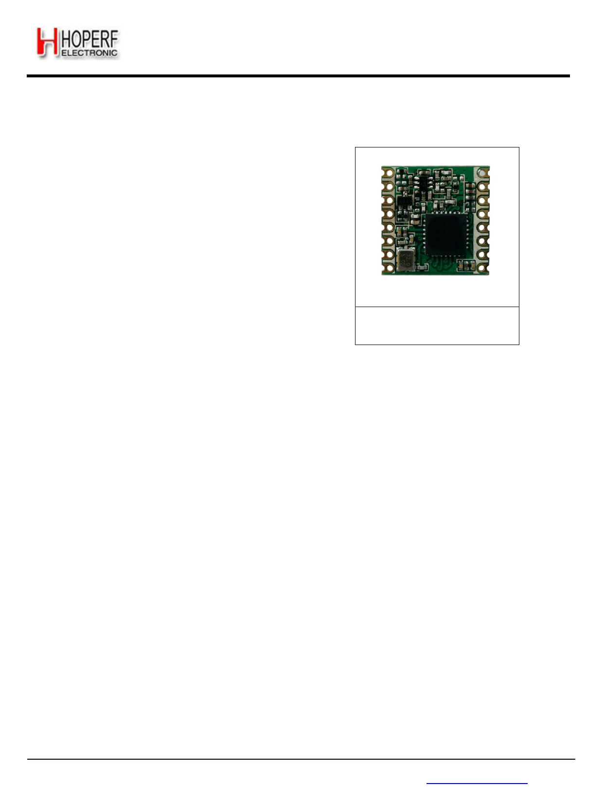
| Descripción | (RFM95 - RFM98) Low Power Long Range Transceiver Module | |
| Fabricantes | HOPERF | |
| Logotipo | ||
Hay una vista previa y un enlace de descarga de RFM96 (archivo pdf) en la parte inferior de esta página. Total 70 Páginas | ||
|
No Preview Available !
RFM95/96/97/98(W)
RFM95/96/97/98(W) - Low Power Long Range Transceiver Module V1.0
GENERAL DESCRIPTION
The RFM95/96/97/98(W) transceivers feature the
LoRaTM long range modem that provides ultra-long range
spread spectrum communication and high interference
immunity whilst minimising current consumption.
Using Hope RF‟s patented LoRaTM modulation technique
RFM95/96/97/98(W) can achieve a sensitivity of over -
148dBm using a low cost crystal and bill of materials. The
high sensitivity combined with the integrated +20 dBm
power amplifier yields industry leading link budget
making it optimal for any application requiring range or
robustness. LoRaTM also provides significant advantages in
both blocking and selectivity over conventional modulation
techniques, solving the traditional design compromise
between range, interference immunity and energy
consumption.
RFM95/96/97/98(W)
These devices also support high performance (G)FSK
modes for systems including WMBus, IEEE802.15.4g. The
RFM95/96/97/98(W) deliver exceptional phase noise,
selectivity, receiver linearity and IIP3 for significantly
lower current consumption than competing devices.
KEY PRODUCT FEATURES
LoRaTM Modem.
168 dB maximum link budget.
+20 dBm - 100 mW constant RF output vs. V supply.
+14 dBm high efficiency PA.
Programmable bit rate up to 300 kbps.
High sensitivity: down to -148 dBm.
Bullet-proof front end: IIP3 = -12.5 dBm.
Excellent blocking immunity.
Low RX current of 10.3 mA, 200 nA register retention.
Fully integrated synthesizer with a resolution of 61 Hz.
FSK, GFSK, MSK, GMSK, LoRaTM and OOK modulation.
Built-in bit synchronizer for clock recovery.
Preamble detection.
127 dB Dynamic Range RSSI.
Automatic RF Sense and CAD with ultra-fast AFC.
Packet engine up to 256 bytes with CRC.
Built-in temperature sensor and low battery indicator.
Modue Size:16*16mm
APPLICATIONS
Automated Meter Reading.
Home and Building Automation.
Wireless Alarm and Security Systems.
Industrial Monitoring and Control
Long range Irrigation Systems
Page 1
Tel: +86-755-82973805 Fax: +86-755-82973550 E-mail: [email protected] http://www.hoperf.com
Free Datasheet http://www.datasheet4u.com/
1 page 
Section
RFM95/96/97/98(W)
Page
Table 1. RFM95/96/97/98(W) Device Variants and Key Parameters .............................................................................10
Table 2. Absolute Maximum Ratings .............................................................................................................................12
Table 3. Operating Range .............................................................................................................................................12
Table 4. Power Consumption Specification ...................................................................................................................13
Table 5. Frequency Synthesizer Specification ..............................................................................................................13
Table 6. FSK/OOK Receiver Specification ....................................................................................................................14
Table 7. Transmitter Specification .................................................................................................................................15
Table 8. LoRa Receiver Specification. ..........................................................................................................................17
Table 9. Digital Specification .........................................................................................................................................19
Table 10. Example LoRaTM Modem Performances .....................................................................................................22
Table 11. Range of Spreading Factors ..........................................................................................................................24
Table 12. Cyclic Coding Overhead ................................................................................................................................24
Table 13. LoRaTM Operating Mode Functionality .........................................................................................................31
Table 14. LoRa CAD Consumption Figures ..................................................................................................................40
Table 15. DIO Mapping LoRaTM Mode .........................................................................................................................41
Table 16. Bit Rate Examples .........................................................................................................................................42
Table 17. Preamble Detector Settings ...........................................................................................................................48
Table 18. RxTrigger Settings to Enable Timeout Interrupts ..........................................................................................49
Table 19. Basic Transceiver Modes ..............................................................................................................................50
Table 20. Receiver Startup Time Summary ..................................................................................................................51
Table 21. Receiver Startup Options ..............................................................................................................................54
Table 22. Sequencer States ..........................................................................................................................................55
Table 23. Sequencer Transition Options .......................................................................................................................56
Table 24. Sequencer Timer Settings .............................................................................................................................58
Table 25. Status of FIFO when Switching Between Different Modes of the Chip .........................................................62
Table 26. DIO Mapping, Continuous Mode ...................................................................................................................64
Table 27. DIO Mapping, Packet Mode ..........................................................................................................................64
Table 28. CRC Description ...........................................................................................................................................72
Table 29. Power Amplifier Mode Selection Truth Table ................................................................................................78
Table 30. High Power Settings ......................................................................................................................................79
Table 31. Operating Range, +20dBm Operation ...........................................................................................................79
Table 32. Operating Range, +20dBm Operation ...........................................................................................................79
Table 33. Trimming of the OCP Current ........................................................................................................................80
Table 34. LNA Gain Control and Performances ............................................................................................................81
Table 35. RssiSmoothing Options .................................................................................................................................82
Table 36. Available RxBw Settings ................................................................................................................................82
Table 37. Registers Summary .......................................................................................................................................84
Table 38. Register Map .................................................................................................................................................87
Table 39. Low Frequency Additional Registers ...........................................................................................................100
Page 5
Tel: +86-755-82973805 Fax: +86-755-82973550 E-mail: [email protected] http://www.hoperf.com
Free Datasheet http://www.datasheet4u.com/
5 Page 
WIRELESS & SENSING
1.4. Pin Description
Number
Name
1 GND
2 MISO
3 MOSI
4 SCK
5 NSS
6 RESET
7 DIO5
8 GND
9 ANT
10 GND
11 DIO3
12 DIO4
13 3.3V
14 DIO0
15 DIO1
16 DIO2
Type
-
I
O
I
I
I/O
I/O
-
-
-
I/O
I/O
-
I/O
I/O
I/O
RFM95/96/97/98(W)
PRELIMINARY
DATASHEET
Description
Description Stand Alone Mode
Ground
SPI Data output
SPI Data input
SPI Clock input
SPI Chip select input
Reset trigger input
Digital I/O, software configured
Ground
RF signal output/input.
Ground
Digital I/O, software configured
Digital I/O, software configured
Supply voltage
Digital I/O, software configured
Digital I/O, software configured
Digital I/O, software configured
Tel: +86-755-82973805 Fax: +86-755-82973550 E-mail: [email protected] http://www.hoperf.com
Page 11
Free Datasheet http://www.datasheet4u.com/
11 Page | ||
| Páginas | Total 70 Páginas | |
| PDF Descargar | [ Datasheet RFM96.PDF ] | |
Hoja de datos destacado
| Número de pieza | Descripción | Fabricantes |
| RFM92W | (RFM92W / RFM93W) Low Power Long Range Transceiver Module | HOPERF |
| RFM93W | (RFM92W / RFM93W) Low Power Long Range Transceiver Module | HOPERF |
| RFM95 | (RFM95 - RFM98) Low Power Long Range Transceiver Module | HOPERF |
| RFM95W | Low Power Long Range Transceiver Module | HOPERF |
| Número de pieza | Descripción | Fabricantes |
| SLA6805M | High Voltage 3 phase Motor Driver IC. |
Sanken |
| SDC1742 | 12- and 14-Bit Hybrid Synchro / Resolver-to-Digital Converters. |
Analog Devices |
|
DataSheet.es es una pagina web que funciona como un repositorio de manuales o hoja de datos de muchos de los productos más populares, |
| DataSheet.es | 2020 | Privacy Policy | Contacto | Buscar |