|
|
|
PDF NE545 Data sheet ( Hoja de datos )
| Número de pieza | NE545 | |
| Descripción | Dolby B Noise Processor | |
| Fabricantes | Signetics | |
| Logotipo | ||
Hay una vista previa y un enlace de descarga de NE545 (archivo pdf) en la parte inferior de esta página. Total 20 Páginas | ||
|
No Preview Available !
EiInEtiEf,
545DOLBNY.OBISPEROCESSOR
LINEAINRTEGRACIEIRDCUITS
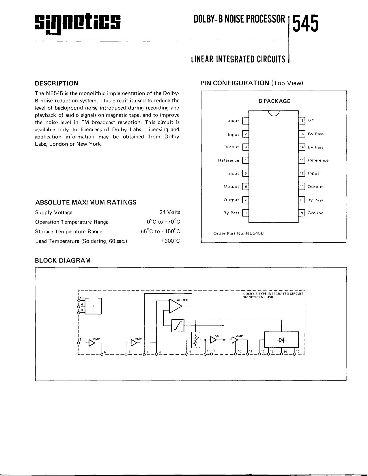
DESCRIPTION
T h e N E 5 4 5 i s t h e m o n o l i t h i c i m p l e m e n t a t i o no f t h e D o l b y "
B n o i s er e d u c t i o n s y s t e m .T h i s c i r c u i t i s u s e dt o r e d u c et h e
levelof background noise introduced during recording and
p l a y b a c ko f a u d i o s i g n a l so n m a g n e t i ct a p e ,a n d t o i m p r o v e
the noise level in FM broadcastreception.This circuit is
a v a i l a b l eo n l y t o l i c e n c e e so f D o l b y L a b s . L i c e n s i n ga n d
application information may be obtained from Dolby
Labs.London or New York.
A B S O L U T EM A X IM U MR A T I N G S
Supply Voltage
24 Volts
O p e r a t i o nT e m p e r a t u r eR a n g e
9"6 1e+70"C
S t o r a g eT e m p e r a t u r eR a n g e
65"C to +i50"C
L e a dT e m p e r a t u r e( S o l d e r i n g ,6 0 s e c . )
+300"C
B L O C KD I A G R A M
P I N C O N F I G U R A T I O N( T o pV i e w )
B PACKAGE
Input
Input
Output
Reference
lnput
Output
O utput
By Pass
By Pass
By Pass
Reference
Input
Output
By Pass
G round
Order Part No. NE545B
D O L B YA T Y P EI N T E G R A T ECDI R C U I II
S I G N E T I CNSE 5 4 5 A
15 J
Free Datasheet http://www.datash
1 page 
T Y P I C A LP E RF O R M A N C EC U R V E S
F I G U R E1 3
B A C K - T O - B A C KF R E O U E N C YRE S P O N S E
V E R S U ST E M P E R A T U R E
ENcoDEAT +25"cAND -3odB
+50
9
3o
E;
25
2dB
S I G N E T I C SD O L B Y - BN O I S EP R O C E S S O RI 5 4 5
F I G U R E1 4
B A C K - T O . B A C KF R E O U E N C YR E S P O N S E
V E R S U ST E M P E R A T U R E
ENcoDEAT +25"9AND -4odB
01 I
10
F R € O U E N C Yl k H / )
F I G U R E1 5
L O WL E V E LF R E O U E N C YR E S P O N S E
0l I t0 too
T U F O U f N C Yl [ H / ]
F I G U R E1 6
M A X I M U MO U T P U TS W I N G
V E B S U SF R E Q U E N C Y
R E F .= 1 % T H D
! roo
-
6
l
=44
F I G U R E1 7
E N C O D EC H A R A C T E RI S T I C S
F I G U R E1 8
L E V E LM I S M A T C HR E S P O N S E
2 d B L O S SB E T W E E NE N C O D EA N D D E C O D E
a '/\)
Free Datasheet http://www.datasheet4
5 Page 
S I G N E T I C SD O L B Y - BN O I S EP R O C E S S O RI 5 4 5
F I G U R E2 7
I M P E D A N C EC O N V E R T E R
BEFERFNCL
VOLTAGF
N O T E :A L L R E S I S T O RS T A N D A R DA N D A R E f u l E A S U R E IDN O H M S
C I R C U I TD E S C R I P T I O N( c o n ' t . )
Amplifier'A'(Figure 27) is a unity gain impedance
converter.providing high input and a given output impe-
d a n c e .A D a r l i n g t o nc o n fi g u r a t i o ni s u s e df o r m i n i m u m b i a s
current, keeping the output offset with respectto the
r e f e r e n c ev o l t a g et o a m i n i m u m . R 2 1 g i v e st h e a p p r o p r i a t e
s o u r c e i m p e d a n c ef o r t h e e x t e r n a l l o w p a s sf i l t e r r e q u i r e d
t o e l i m i n a t e s u p e r s o n i cs i g n a l so r i g i n a t i n gf r o m F M t u n e r s
or from the bias and erase oscillators of tape recorders.
One of the most challengingaspectsof the lC design
w a s t h e d e v e l o p m e n to f a v a r i a b l er e s i s t o r( b l o c k F ) w i t h
a w i d e d y n a m i c r a n g e a n d a r e s i s t a n c ev e r s u s c o n t r o l
voltage law similar to that of the field effect transistor
e m p l o y e d i n t h e d i s c r e t ec o m p o n e n t c i r c u i t .
The drain source conductance Gp5 of a field effect
transistor operating as a variable resistor is given by
G
o
s=
2
.
I
i
ns
ix
s
Vo'
[
(
v
c
s
-
Vns
---:
2
:
)
-vYn-l
where IDSS is drain saturationcurrent, Vp is gate pinch-
o f f v o l t a g e , V 6 5 i s g a t e - s o u r c eb i a s , V p 5 i s d r a i n - s o u r c e
voltage.
Provided the signal level applied to the device is small,
G p g i st h e r e f o r ea l i n e a rf u n c t i o n o f t h e g a t e - s o u r c veo l t a g e .
F o r a f o r w a r d b i a s e dj u n c t i o n , t h e s l o p e r e s i s t a n c eR J i s
givenby
KT
R l=-
ol
w h e r e k i s B o l t z m a n n ' sc o n s t a n t ,T i s a b s o l u t et e m p e r a t u r e ,
q is electronic charge,and I is forward current through
junction.
H e n c e t h e s l o p e c o n d u c t a n c eo f t h e j u n c t i o n G 1 i s a l i n e a r
function of the forward current, and it is possibleto match
the FET.
T h e c h o s e nv a r i a b l er e s i s t o rc i r c u i t i s s h o w n i n i t s b a s i cf o r m
in Figure28. BVvaryingthe currentthrough the differential
pair 01, 02 with the current sources1 and 2, the input
r e s i s t a n c ea t p o i n t 3 c h a n g e sa n d i t s v a l u e i s a p p r o x i m a t e l y
26 X 10'3
2 X_ohms
at room temoerature.
Free Datasheet http://www.datasheet4
11 Page | ||
| Páginas | Total 20 Páginas | |
| PDF Descargar | [ Datasheet NE545.PDF ] | |
Hoja de datos destacado
| Número de pieza | Descripción | Fabricantes |
| NE5410 | 10-Bit high-speed multiplying D/A converter | Philips |
| NE5410F | 10-Bit high-speed multiplying D/A converter | Philips |
| NE542 | Dual Low-Noise Preamplifier | Ideal |
| NE542 | Dual Low-Noise Preamplifier | Philips |
| Número de pieza | Descripción | Fabricantes |
| SLA6805M | High Voltage 3 phase Motor Driver IC. |
Sanken |
| SDC1742 | 12- and 14-Bit Hybrid Synchro / Resolver-to-Digital Converters. |
Analog Devices |
|
DataSheet.es es una pagina web que funciona como un repositorio de manuales o hoja de datos de muchos de los productos más populares, |
| DataSheet.es | 2020 | Privacy Policy | Contacto | Buscar |