|
|
|
PDF AT7601F Data sheet ( Hoja de datos )
| Número de pieza | AT7601F | |
| Descripción | Printer Port Controller | |
| Fabricantes | AME | |
| Logotipo | ||
Hay una vista previa y un enlace de descarga de AT7601F (archivo pdf) en la parte inferior de esta página. Total 35 Páginas | ||
|
No Preview Available !
AME, Inc.
AT7601F
1. General Description
The AT7601F is a Printer Port Controller. It supports
the existing Centronics printer and IEEE 1284 compat-
ible parallel ports
2. Features
l 5V parallel port I/O
l IBM PC compatible printer port
l PS/2 compatible bi-directional parallel port
l IEEE 1284 compatible Enhanced Parallel
Port (EPP)
l IEEE 1284 compatible Extended Capabili
ties Port (ECP)
l Legacy parallel ports
Printer Port Controller
Order Information
AT7601F- Commercial Standard
AT7601FG- Green Device with Commercial Standard
Part Number
Marking
AT7601FG
AT7601FG
yyww AA
Note: yyww represent the date code.
Package
LQFP-48
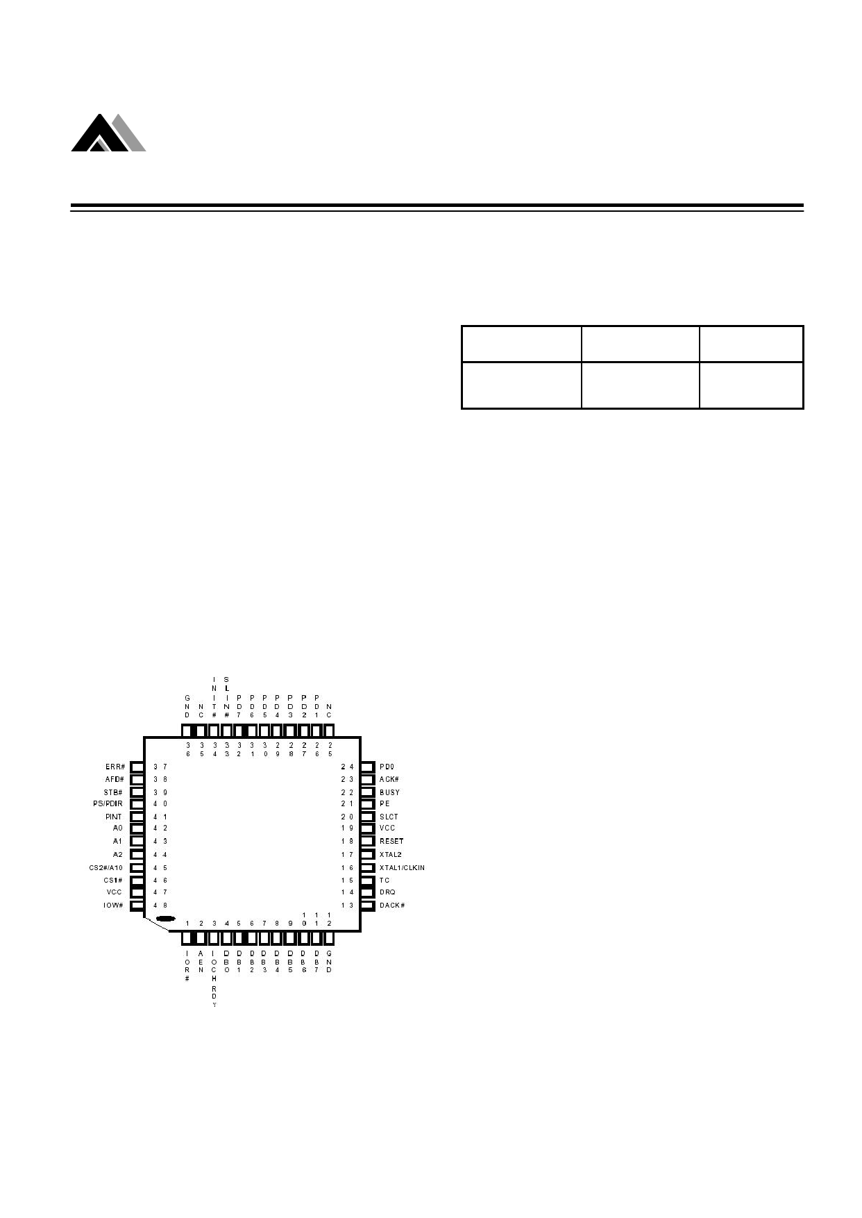
3. Pin Configuration
AT7601F
Figure 1. AT7601F Pin Diagram (Top View)
Rev. B.02
1
Free Datasheet http://www.datasheet4u.com/
1 page 
AME, Inc.
AT7601F
5-2 Enhanced Parallel Port(EPP)
SPP Name EPP Name
STB#
PD[0:7]
ACK#
Write#
PD [0: 7]
INTR
BUSY
PE
SLCT
AFD
ERR#
INIT#
SLIN#
Wait#
PE
Select
DataSTB#
Error#
INIT#
AddrSTB#
Printer Port Controller
I/O Type
EPP Description
O Active low; It indicates a write operation.
I/O Bi-directional EPP byte wide address and data bus.
I Interrupt, Active high; Peripheral generates an interrupt to
the host.
Active low; it is handshake signal. When low, it indicates
I that the device is ready for next transfer, when high, it
indicates that the data transfer is complete.
I Paper End; Same as SPP mode.
I Printer selected status; Same as SPP mode.
O Data Strobe ; Active low; it indicates a data read or write
operation.
I Error; Same as SPP mode.
O
Active low; The EPP device is reset to its initial operating
mode.
O Address Strobe ; Active low; It indicates an address read
or write operation.
Table 5. EPP Pin Descriptions
A2 A1 A0
Register
0 0 0 Data Port
0 0 1 Printer Status Port
0 1 0 Printer Control Port
0 1 1 EPP Address Port
1 0 0 EPP Data Port 0
1 0 1 EPP Data Port 1
1 1 0 EPP Data Port 2
1 1 1 EPP Data Port 3
Table 6. EPP Pin Descriptions
Note 1: These registers are in all mode
Note 2: These registers are in EPP mode
Note 3: For EPP mode, IOCHRDY must be connect to the ISA BUS
Rev. B.02
Note
1
1
1
2,3
2,3
2,3
2,3
2,3
5
Free Datasheet http://www.datasheet4u.com/
5 Page 
AME, Inc.
AT7601F
Printer Port Controller
Pin Name ECP Mode Name I/O Type
STB#
HostClk
O
PD [7:0]
ACK#
D0-D7
PeriphClk
I/O
I
Busy
PeriphAck
I
PError
AckReverse#
SLCT
Xflag
I
I
AFD#
HostAck
O
Fault#
PeriphReq#
I
INIT#
SLIN#
ReverseReq#
ECPMode
O
O
Description
During write operations STB# registers data or address
into the slave on the asserting edge. These signal
handshakes with Busy.
These signals contain address or data or RLE data.
This signal indicates valid data driven by the peripheral when
asserted. This signal handshakes with AFD# in reverse.
This signal deasserts to indicate that the peripheral can
accept data. It indicates whether the data lines contain
ECP command information or data in the reverse
direction. When in reverse direction, normal data are
transferred when Busy (PeriphAck) is high and an 8-bit
command is transferred when it is low.
This signal is used to acknowledge a change in the direction
of the transfer (asserted = forward). The peripheral drives
this signal low to acknowledge ReverseReq#. The host
relies upon AckReverse# to determine when it is permitted to
drive the data bus.
Indicates printer on line.
Requests a byte of data from the peripheral when it is
asserted. This signal indicates whether the data lines
contain ECP address or data in the forward direction.
When in forward direction, normal data are transferred when
AFD# (HostAck) is high and an 8-bit command is
transferred when it is low.
Generates an error interrupt when it is asserted. This
signal is valid only in the forward direction. The peripheral
is permitted (but not required) to drive this pin low to
request a reverse transfer during ECP Mode.
This signal sets the transfer direction (asserted = reverse,
deasserted = forward). This pin is driven low to place the
channel in the reverse direction.
This signal is always deasserted in ECP mode.
Table 8. ECP Pin Descriptions
Rev. B.02
11
Free Datasheet http://www.datasheet4u.com/
11 Page | ||
| Páginas | Total 35 Páginas | |
| PDF Descargar | [ Datasheet AT7601F.PDF ] | |
Hoja de datos destacado
| Número de pieza | Descripción | Fabricantes |
| AT7601F | Printer Port Controller | AME |
| Número de pieza | Descripción | Fabricantes |
| SLA6805M | High Voltage 3 phase Motor Driver IC. |
Sanken |
| SDC1742 | 12- and 14-Bit Hybrid Synchro / Resolver-to-Digital Converters. |
Analog Devices |
|
DataSheet.es es una pagina web que funciona como un repositorio de manuales o hoja de datos de muchos de los productos más populares, |
| DataSheet.es | 2020 | Privacy Policy | Contacto | Buscar |