|
|
|
PDF SDR-120 Data sheet ( Hoja de datos )
| Número de pieza | SDR-120 | |
| Descripción | 120W Single Output Industrial DIN RAIL | |
| Fabricantes | Mean Well | |
| Logotipo | ||
Hay una vista previa y un enlace de descarga de SDR-120 (archivo pdf) en la parte inferior de esta página. Total 3 Páginas | ||
|
No Preview Available !
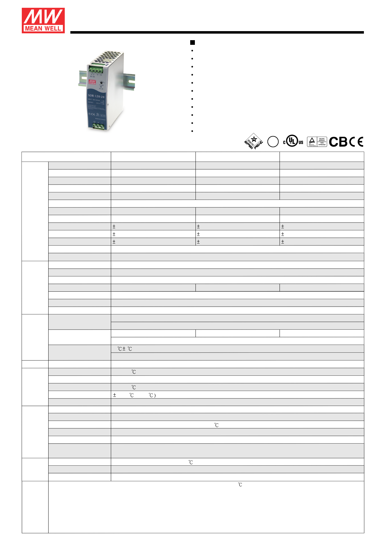
120W Single Output Industrial DIN RAIL with PFC Function
SDR-120 series
Features :
High efficiency 91% and low power dissipation
150% peak load capability
Built-in active PFC function, PF>0.93
Protections: Short circuit / Overload / Over voltage / Over temperature
Cooling by free air convection
Can be installed on DIN rail TS-35/7.5 or 15
UL 508 (industrial control equipment) approved
EN61000-6-2(EN50082-2) industrial immunity level
Built-in DC OK relay contact
100% full load burn-in test
3 years warranty
SPECIFICATION
SEM PQ
I F47
GL
MODEL
SDR-120-12
SDR-120-24
SDR-120-48
DC VOLTAGE
12V
24V
48V
RATED CURRENT
10A
5A
2.5A
CURRENT RANGE
0 ~ 10A
0 ~ 5A
0 ~ 2.5A
RATED POWER
120W
120W
120W
PEAK CURRENT
15A
7.5A 3.75A
PEAK POWER Note.6
180W (3 sec.)
OUTPUT RIPPLE & NOISE (max.) Note.2 100mVp-p
100mVp-p
120mVp-p
VOLTAGE ADJ. RANGE
12 ~ 14V
24 ~ 28V
48 ~ 55V
VOLTAGE TOLERANCE Note.3 1.0% 1.0% 1.0%
LINE REGULATION
0.5%
0.5%
0.5%
LOAD REGULATION
1.0%
1.0%
1.0%
SETUP, RISE TIME
1500ms, 60ms/230VAC 3000ms, 60ms/115VAC at full load
HOLD UP TIME (Typ.)
20ms/230VAC 20ms/115VAC at full load
VOLTAGE RANGE Note.7 88 ~ 264VAC 124 ~ 370VDC
FREQUENCY RANGE
47 ~ 63Hz
INPUT
POWER FACTOR (Typ.)
EFFICIENCY (Typ.)
0.93/230VAC
89%
0.96/115VAC at full load
http://www.DataSheet4U.com/
91%
90.5%
AC CURRENT (Typ.)
1.4A/115VAC 0.7A/230VAC
INRUSH CURRENT (Typ.) 35A/115VAC 70A/230VAC
LEAKAGE CURRENT
<1mA / 240VAC
OVERLOAD
Normally works within 110 ~ 150% rated output power for more than 3 seconds and then shut down o/p voltage
>150% rated power, constant current limiting with auto-recovery within 3 seconds and shut down o/p voltage after 3 seconds
PROTECTION OVER VOLTAGE
14 ~ 17V
29 ~ 33V
Protection type : Shut down o/p voltage, re-power on to recover
56 ~ 65V
OVER TEMPERATURE
95 5 (TSW : detect on heatsink of power switch)
Protection type : Shut down o/p voltage, recovers automatically after temperature goes down
FUNCTION DC OK REALY CONTACT RATINGS (max.) 60Vdc/0.3A, 30Vdc/1A, 30Vac/0.5A resistive load
WORKING TEMP.
-25 ~ +70 (Refer to output load derating curve)
WORKING HUMIDITY
20 ~ 95% RH non-condensing
ENVIRONMENT STORAGE TEMP., HUMIDITY -40 ~ +85 , 10 ~ 95% RH
TEMP. COEFFICIENT
0.03%/ (0 ~ 50
VIBRATION
Component:10 ~ 500Hz, 2G 10min./1cycle, 60min. each along X, Y, Z axes; Mounting: Compliance to IEC60068-2-6
SAFETY STANDARDS
UL508, TUV EN60950-1 approved
WITHSTAND VOLTAGE
I/P-O/P:3KVAC I/P-FG:1.5KVAC O/P-FG:0.5KVAC O/P-DC OK:0.5KVAC
SAFETY & ISOLATION RESISTANCE I/P-O/P, I/P-FG, O/P-FG:>100M Ohms / 500VDC / 25 / 70% RH
EMC EMI CONDUCTION & RADIATION Compliance to EN55022 (CISPR22) Class B
(Note 4) HARMONIC CURRENT
Compliance to EN61000-3-2,-3
EMS IMMUNITY
Compliance to EN61000-4-2,3,4,5,6,8,11, ENV50204, EN55024, EN61000-6-2 (EN50082-2), EN61204-3, heavy industry level,
criteria A, SEMI F47, GL approved
MTBF
289.9Khrs min. MIL-HDBK-217F (25 )
OTHERS DIMENSION
40*125.2*113.5mm (W*H*D)
NOTE
PACKING
0.67Kg; 20pcs/14.4Kg/1.16CUFT
1. All parameters NOT specially mentioned are measured at 230VAC input, rated load and 25 of ambient temperature.
2. Ripple & noise are measured at 20MHz of bandwidth by using a 12" twisted pair-wire terminated with a 0.1uf & 47uf parallel capacitor.
3. Tolerance : includes set up tolerance, line regulation and load regulation.
4. The power supply is considered a component which will be installed into a final equipment. The final equipment must be re-confirmed that it still meets
EMC directives.
5. Installation clearances : 40mm on top, 20mm on the bottom, 5mm on the left and right side are recommended when loaded permanently with full power.
In case the adjacent device is a heat source, 15mm clearance is recommended.
6. 3 seconds max., please refer to peak loading curves.
7. Derating may be needed under low input voltage. Please check the derating curve for more details.
File Name:SDR-120-SPEC 2010-12-07
1 page | ||
| Páginas | Total 3 Páginas | |
| PDF Descargar | [ Datasheet SDR-120.PDF ] | |
Hoja de datos destacado
| Número de pieza | Descripción | Fabricantes |
| SDR-120 | 120W Single Output Industrial DIN RAIL | Mean Well |
| Número de pieza | Descripción | Fabricantes |
| SLA6805M | High Voltage 3 phase Motor Driver IC. |
Sanken |
| SDC1742 | 12- and 14-Bit Hybrid Synchro / Resolver-to-Digital Converters. |
Analog Devices |
|
DataSheet.es es una pagina web que funciona como un repositorio de manuales o hoja de datos de muchos de los productos más populares, |
| DataSheet.es | 2020 | Privacy Policy | Contacto | Buscar |