|
|
|
PDF LTC4156 Data sheet ( Hoja de datos )
| Número de pieza | LTC4156 | |
| Descripción | Dual-Input Power Manager / 3.5A LiFePO4 Battery Charger | |
| Fabricantes | Linear Technology | |
| Logotipo | ||
Hay una vista previa y un enlace de descarga de LTC4156 (archivo pdf) en la parte inferior de esta página. Total 30 Páginas | ||
|
No Preview Available !
LTC4156
Dual-Input Power Manager/
w3.i5thAI2LCiFeCPoOn4trBoal tatenrdy
Charger
USB OTG
FEATURES
DESCRIPTION
n High Efficiency Charger Capable of 3.5A
Charge Current
n Charge Control Algorithm Specifically Designed for
LiFePO4 Batteries (Lithium Iron Phosphate)
n Monolithic Switching Regulator Makes Optimal Use
of Limited Power and Thermal Budget
n Dual Input Overvoltage Protection Controller
n Priority Multiplexing for Multiple Inputs
n I2C/SMBus Control and Status Feedback
n NTC Thermistor ADC for Temperature Dependent
Charge Algorithms (JEITA)
n Instant-On Operation with Low Battery
n Battery Ideal Diode Controller for Power
Management
n USB On-The-Go Power Delivery to the USB Port
n Four Float Voltage Settings (3.45V, 3.55V, 3.6V, 3.8V)
n 28-Lead 4mm × 5mm QFN Package
APPLICATIONS
n Portable Medical Devices
n Portable Industrial Devices
n Backup Devices
L, LT, LTC, LTM, Linear Technology and the Linear logo are registered trademarks and
PowerPath and Bat-Track are trademarks of Linear Technology Corporation. All other trademarks
are the property of their respective owners.
The LTC®4156 is a 15 watt I2C controlled power manager
with PowerPath™ instant-on operation, high efficiency
switching battery charging and USB compatibility. The
LTC4156 seamlessly manages power distribution from
two 5V sources, such as a USB port and a wall adapter, to
a single-cell rechargeable lithium iron phosphate battery
and a system load.
The LTC4156’s switching battery charger automatically
limits its input current for USB compatibility, or may
draw up to 3A from a high power wall adapter. The high
efficiency step-down switching charger is designed to
provide maximum power to the application and reduced
heat in high power density applications.
I2C adjustability of input current, charge current, battery
float voltage, charge termination, and many other param-
eters allows maximum flexibility. I2C status reporting of
keywww.DataSheet.co.kr system and charge parameters facilitates intelligent
control decisions. USB On-The-Go support provides 5V
power back to the USB port without any additional com-
ponents. A dual-input, priority multiplexing, overvoltage
protection circuit guards the LTC4156 from high voltage
damage on the VBUS pin.
The LTC4156 is available in the low profile (0.75mm)
28-lead 4mm × 5mm QFN surface mount package.
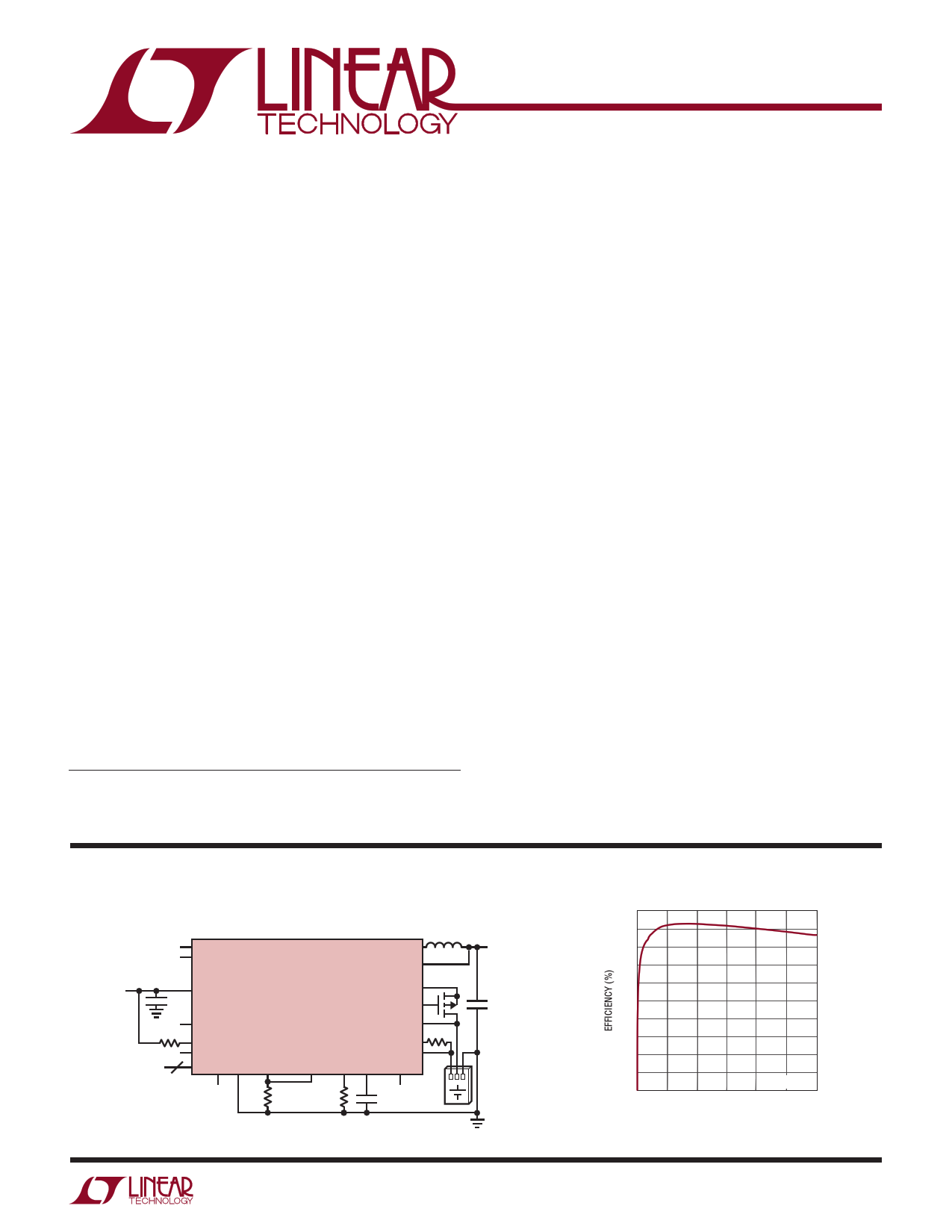
TYPICAL APPLICATION
I2C Controlled High Power Battery Charger/USB Power Manager
WALLSNS
WALLGT
SW
VOUT
1µH
TO
SYSTEM
LOAD
VIN VBUS
10µF
LTC4156
CHGSNS
BATGATE
USBGT
BATSNS
3.6k 100k
USBSNS
NTCBIAS
3
ID NTC
I2C IRQ GND CLPROG2 CLPROG1 PROG VC OVGCAP
22µF
1.21k
499Ω
47nF
4156 TA01a
Switching Regulator Efficiency
100
90
80
70
60
50
40
30
20
10
0
0
VBAT = 3.3V
0.5 1.0 1.5 2.0 2.5 3.0
LOAD CURRENT (A)
4156 TA01b
4156f
1
Datasheet pdf - http://www.DataSheet4U.net/
1 page 
LTC4156
ELECTRICAL CHARACTERISTICS The l denotes the specifications which apply over the specified operating
junction temperature
RCLPROG1 = RCLPROG2
range, otherwise
= 1.21k, RPROG =
4s9p9eΩcif,icuantlieosnssoatrheerawt iTsAe≈noTtJe=d.25°C
(Note
2).
VBUS
=
5V,
BATSNS
=
3.3V,
DVCC
=
3.3V,
SYMBOL
IVOUT
VPROG
VRECHRG
tTERMINATE
VLOWBAT
tBADBAT
VC/x
hPROG
hCLPROG1
(Note 4)
PARAMETER
VOUT Current Available Before
Loading Battery
PROG Pin Servo Voltage
Recharge Battery Threshold
Voltage
Safety Timer Termination Period
Selected by I2C Control. Timer
Starts When BATSNS ≥ VFLOAT
Threshold Voltage
Bad Battery Termination Time
Full Capacity Charge Indication
PROG Voltage Selected by I2C
Control
Ratio of ICHGSNS to PROG Pin
Current
Ratio of Measured VBUS Current to
CLPROG1 Sense Current
CONDITIONS
2.5mA IVBUS Mode (USB Suspend)
100mA IVBUS Mode, BAT = 3.3V
500mA IVBUS Mode, BAT = 3.3V
600mA
700mA
800mA
IIIVVVBBBUUUSSS
Mode,
Mode,
Mode,
BAT
BAT
BAT
=
=
=
3.3V
3.3V
3.3V
900mA IVBUS Mode, BAT = 3.3V
1.00A IVBUS Mode, BAT = 3.3V
1.25A
1.50A
IIVVBBUUSS
Mode,
Mode,
BAT
BAT
=
=
3.3V
3.3V
1.75A IVBUS Mode, BAT = 3.3V
2.00A IVBUS Mode, BAT = 3.3V
2.25A
2.50A
2.75A
IIIVVVBBBUUUSSS
Mode,
Mode,
Mode,
BAT
BAT
BAT
=
=
=
3.3V
3.3V
3.3V
3.00A IVBUS Mode, BAT = 3.3V
12.50% Charge Current Mode
18.75% Charge Current Mode
25.00% Charge Current Mode
31.25% Charge Current Mode
37.50% Charge Current Mode
43.75% Charge Current Mode
50.00% Charge Current Mode
56.25% Charge Current Mode
62.50% Charge Current Mode
68.75% Charge Current Mode
75.00% Charge Current Modewww.DataSheet.co.kr
81.25% Charge Current Mode
87.50% Charge Current Mode
93.75% Charge Current Mode
100.0% Charge Current Mode (Default)
Threshold Voltage Relative to VFLOAT
0.25-Hour Mode
0.5-Hour Mode
1-Hour Mode (Default)
4-Hour Mode
Rising Threshold
Hysteresis
BATSNS < (VLOWBAT – ΔVLOWBAT)
C/10 Mode (ICHARGE = 10%FS) (Default)
CC//250MMooddee(I(CIHCAHRAGREGE==205%%FFSS))
C/50 Mode (ICHARGE = 2%FS)
CLPROG1 IVBUS Mode
MIN TYP MAX
1 1.3
76
673
810
944
1093
1200
1397
1728
2072
2411
2700
2846
3154
3408
3657
150
225
300
375
450
525
600
675
750
825
900
975
1050
1125
1200
96.6 97.6 98.4
UNITS
mA
mA
mA
mA
mA
mA
mA
mA
mA
mA
mA
mA
mA
mA
mA
mA
mV
mV
mV
mV
mV
mV
mV
mV
mV
mV
mV
mV
mV
mV
mV
%
0.23 0.27 0.30
0.47 0.53 0.59
0.95 1.06 1.17
3.81 4.24 4.66
Hours
Hours
Hours
Hours
2.65 2.8 2.95
130
V
mV
0.47 0.53 0.59
Hours
110 120 130
230 240 250
15 24 33
50 60 70
mV
mV
mV
mV
1000 mA/mA
990 mA/mA
4156f
5
Datasheet pdf - http://www.DataSheet4U.net/
5 Page 
LTC4156
TYPICAL PERFORMANCE CHARACTERISTICS
DVCC
=
3.3V,
RCLPROG1
=
RCLPROG2
=
1.21k,
RPROG
=
499Ω,
unless
otherwise
notedT.A
=
25°C
(Note
2).
VBUS
=
5V,
BATSNS
=
3.3V,
Undervoltage Lockout Thresholds
vs Temperature
4.30
4.25 RISING EDGE NOT MAX
4.20
OVP Charge Pump Output
vs Input Voltage
10
9
Battery Drain Current
vs Battery Voltage
4
SHIP-AND-STORE MODE, DVCC = 0V
SHIP-AND-STORE MODE, DVCC = 3.3V
DVCC = 0V
3 DVCC = 3.3V
4.15 RISING EDGE MAX
8
4.10 FALLING EDGE NOT MAX
2
4.05
FALLING EDGE MAX
4.00
7
1
3.95
–40 –25 –10 5 20 35 50 65 80 95 110 125
TEMPERATURE (°C)
4155 G19
6
3.5 4.0 4.5
5.0 5.5
6.0 6.5
INPUT VOLTAGE (V)
4155 G20
0
2.4 2.7 3.0 3.3 3.6 3.9
BATTERY VOLTAGE (V)
4156 G22
CLPROG Voltage vs VBUS Current
1.4
3A INPUT CURRENT LIMIT MODE
1.2
1.0
0.8
0.6
0.4
0.2
0
0 0.5 1.0 1.5 2.0 2.5 3.0 3.5
VBUS CURRENT (A)
4155 G23
CLPROG Voltage vs VOUT Current
1.4 3A INPUT CURRENT LIMIT MODE
1.2
1.0
0.8
www.DataSheet.co.kr
0.6
0.4
0.2
0
0 0.5 1.0 1.5 2.0 2.5 3.0 3.5
VOUT CURRENT (A)
4155 G24
VOUT Voltage vs VOUT Current
4.4
3A
4.2 MODE
4.0
900mA MODE
3.8
3.6
500mA
MODE
VBATSNS = 3.7V
BATTERY CHARGER DISABLED
3.4
012
3
VOUT CURRENT (A)
4
4155 G33
4156f
11
Datasheet pdf - http://www.DataSheet4U.net/
11 Page | ||
| Páginas | Total 30 Páginas | |
| PDF Descargar | [ Datasheet LTC4156.PDF ] | |
Hoja de datos destacado
| Número de pieza | Descripción | Fabricantes |
| LTC4150 | Coulomb Counter/ Battery Gas Gauge | Linear Technology |
| LTC4151 | High Voltage I2C Current and Voltage Monitor | Linear Technology |
| LTC4151-1 | High Voltage I2C Current and Voltage Monitor | Linear Technology |
| LTC4155 | Dual-Input Power Manager / 3.5A Li-Ion Battery Charger | Linear Technology |
| Número de pieza | Descripción | Fabricantes |
| SLA6805M | High Voltage 3 phase Motor Driver IC. |
Sanken |
| SDC1742 | 12- and 14-Bit Hybrid Synchro / Resolver-to-Digital Converters. |
Analog Devices |
|
DataSheet.es es una pagina web que funciona como un repositorio de manuales o hoja de datos de muchos de los productos más populares, |
| DataSheet.es | 2020 | Privacy Policy | Contacto | Buscar |