|
|
|
PDF MAX17491 Data sheet ( Hoja de datos )
| Número de pieza | MAX17491 | |
| Descripción | Single-Phase Synchronous MOSFET Driver | |
| Fabricantes | Maxim Integrated Products | |
| Logotipo | ||
Hay una vista previa y un enlace de descarga de MAX17491 (archivo pdf) en la parte inferior de esta página. Total 12 Páginas | ||
|
No Preview Available !
19-5324; Rev 0; 6/10
EVAALVUAAILTAIOBNLEKIT
www.DataSheet4U.com
Single-Phase Synchronous MOSFET Driver
General Description
The MAX17491 is a single-phase synchronous nonin-
verting MOSFET driver. The MAX17491 is intended to
work with controller ICs like the MAX8736, MAX8786, or
MAX17030 in multiphase notebook CPU core regulators.
The regulators can either step down directly from the
battery voltage to create the core voltage or step down
from the main system supply. The single-stage conver-
sion method allows the highest possible efficiency, while
the 2-stage conversion at higher switching frequency
provides the minimum possible physical size.
The low-side driver is optimized to drive 3nF capacitive
loads with 4ns/8ns typical fall/rise times, and the high-
side driver with 8ns/10ns typical fall/rise times.
Adaptive dead-time control prevents shoot-through cur-
rents and maximizes converter efficiency.
The MAX17491 features improved zero crossing and
UVLO performance over the MAX8791/MAX8791B.
The MAX17491 is available in a small, lead-free, 8-pin,
3mm x 3mm TQFN package.
Applications
Notebooks/Desktops/Servers
CPU Core Power Supplies
Multiphase Step-Down Converters
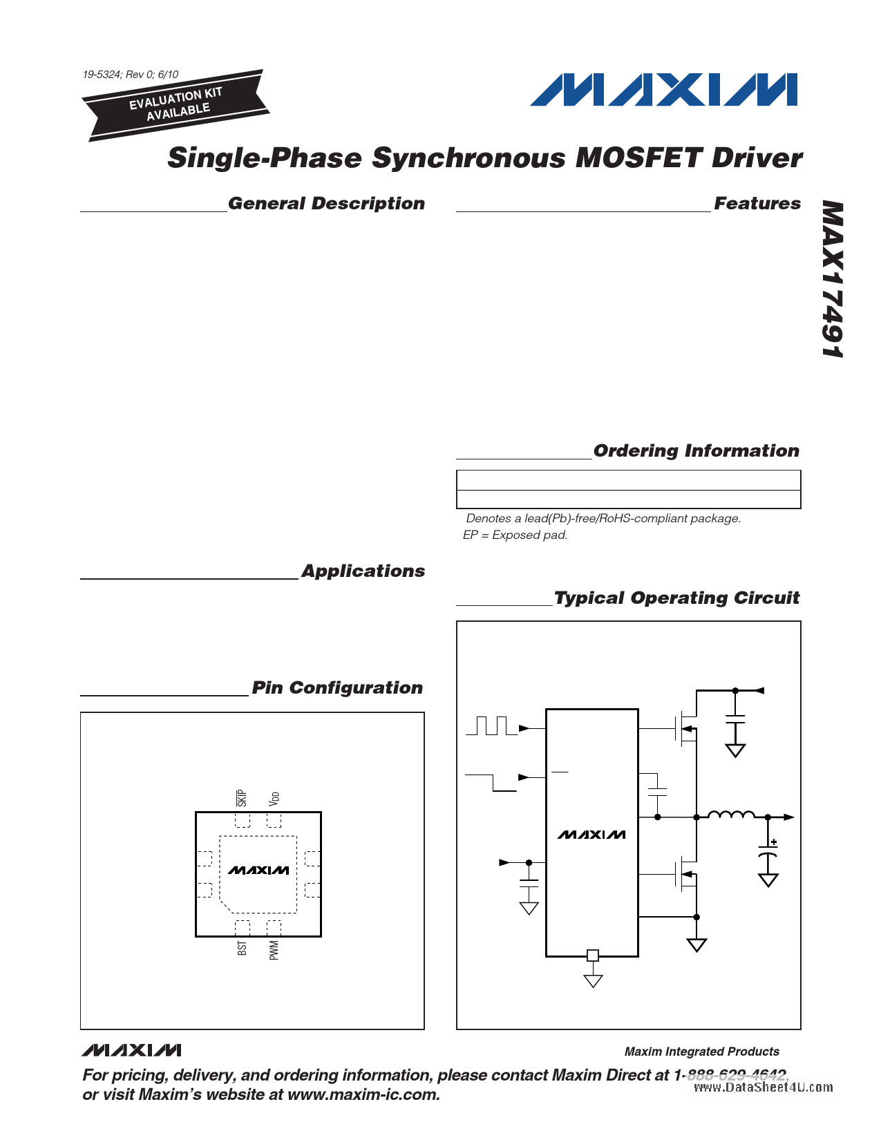
Pin Configuration
Features
♦ Single-Phase Synchronous MOSFET Driver
♦ 0.5Ω Low-Side On-Resistance
♦ 0.7Ω High-Side On-Resistance
♦ 10ns Minimum Guaranteed Dead Time
♦ Integrated Boost “Diode”
♦ 2V to 24V Input Voltage Range
♦ Selectable Pulse-Skipping Mode
♦ Low-Profile, 3mm x 3mm, TQFN Package
Ordering Information
PART
TEMP RANGE
PIN-PACKAGE
MAX17491GTA+ -40°C to +105°C
8 TQFN-EP*
+Denotes a lead(Pb)-free/RoHS-compliant package.
*EP = Exposed pad.
Typical Operating Circuit
INPUT (VIN)
5V TO 24V
TOP VIEW
65
LX 7
DH 8
MAX17491
+ EP
12
4 DL
3 GND
TQFN
PWM DH
PWM SKIP
+5V BIAS
SUPPLY
SKIP BST
LX
MAX17491
VDD
DL
GND
PAD
VOUT (1.45V
AT 20A)
________________________________________________________________ Maxim Integrated Products 1
For pricing, delivery, and ordering information, please contact Maxim Direct at 1-888-629-4642,
or visit Maxim’s website at www.maxim-ic.com.
1 page 
www.DataSheet4U.com
Single-Phase Synchronous MOSFET Driver
Typical Operating Characteristics (continued)
(Circuit of Figure 1, VDD = 5V, CDH = 3nF, CDL = 3nF, TA = +25°C, unless otherwise noted.)
VPWM
VDL
VLX
SWITCHING WAVEFORMS
(PWM = MID TO LOW TO MID)
MAX17491 toc11
5V
5V/div
0
5V
5V/div
0
0
10V/div
0
VDH 10V/div
VPWM
VDL
VLX
VDH
SWITCHING WAVEFORMS
(PWM = HIGH TO MID TO HIGH)
MAX17491 toc12
5V
5V/div
0
0
5V/div
10V
10V/div
0
15V
10V/div
0
Pin Description
PIN NAME
FUNCTION
1
BST
Boost Flying-Capacitor Connection. Gate-drive power supply for DH high-side gate driver. Connect a
0.1μF or 0.22μF capacitor between BST and LX.
PWM Input. Noninverting DH control input from the controller IC:
Logic-high: DH = high (BST), DL = low (PGND).
Midlevel: After the midlevel hold time expires, the controller enters standby mode. DH and DL pulled
2
PWM
low.
Logic-low: DH = low (LX), DL = high (VDD) when SKIP = high.
Internal pullup and pulldown resistors create the midlevel and prevent the controller from triggering an
on-time if this input is left unconnected (not soldered properly) or driven by a high impedance.
3 GND Power Ground for the DL Gate Drivers and Analog Ground. Connect exposed pad to GND.
4 DL PWM Low-Side Gate-Driver Output. Swings between GND and VDD. DL forced high in shutdown.
5
VDD
Supply Voltage Input for the DL Gate Drivers. Connect to 4.2V to 5.5V supply and bypass to GND with a
1μF ceramic capacitor.
Active-Low Pulse-Skipping Mode. Enable pulse-skipping mode (zero-crossing comparator enabled) when
the driver is operating in SKIP mode:
6
SKIP
SKIP = VDD PWM mode
SKIP = GND skip mode
An internal pulldown current pulls the controller into the low-power pulse-skipping state if this input is
left unconnected (not soldered properly) or driven by a high impedance.
7 LX Switching Node and Inductor Connection. Low-power supply for the DH high-side gate driver. LX
connects to the skip-mode zero-crossing comparator.
8 DH External High-Side n-Channel MOSFET Gate-Driver Output. Swings between LX and BST.
— EP Exposed Pad. Connect to ground through multiple vias to reduce the thermal impedance.
_______________________________________________________________________________________ 5
5 Page 
www.DataSheet4U.com
Single-Phase Synchronous MOSFET Driver
PROCESS: BiCMOS
Chip Information
Package Information
For the latest package outline information and land patterns, go
to www.maxim-ic.com/packages. Note that a “+”, “#”, or “-” in
the package code indicates RoHS status only. Package draw-
ings may show a different suffix character, but the drawing per-
tains to the package regardless of RoHS status.
PACKAGE
TYPE
8 TQFN-EP
PACKAGE
CODE
TQ833+1
OUTLINE
LAND
NO. PATTERN NO.
21-0136
90-0066
______________________________________________________________________________________ 11
11 Page | ||
| Páginas | Total 12 Páginas | |
| PDF Descargar | [ Datasheet MAX17491.PDF ] | |
Hoja de datos destacado
| Número de pieza | Descripción | Fabricantes |
| MAX1749 | SOT23 Vibrator Motor Driver | Maxim Integrated |
| MAX17491 | Single-Phase Synchronous MOSFET Driver | Maxim Integrated Products |
| MAX17497A | (MAX17497A/B) AC-DC and DC-DC Peak-Current-Mode Converters | Maxim Integrated Products |
| MAX17497B | (MAX17497A/B) AC-DC and DC-DC Peak-Current-Mode Converters | Maxim Integrated Products |
| Número de pieza | Descripción | Fabricantes |
| SLA6805M | High Voltage 3 phase Motor Driver IC. |
Sanken |
| SDC1742 | 12- and 14-Bit Hybrid Synchro / Resolver-to-Digital Converters. |
Analog Devices |
|
DataSheet.es es una pagina web que funciona como un repositorio de manuales o hoja de datos de muchos de los productos más populares, |
| DataSheet.es | 2020 | Privacy Policy | Contacto | Buscar |