|
|
|
PDF A8512 Data sheet ( Hoja de datos )
| Número de pieza | A8512 | |
| Descripción | LED Backlight Driver | |
| Fabricantes | Allegro Micro Systems | |
| Logotipo | ||
Hay una vista previa y un enlace de descarga de A8512 (archivo pdf) en la parte inferior de esta página. Total 16 Páginas | ||
|
No Preview Available !
A8512www.DataSheet4U.com
LED Backlight Driver for Medium/Large Displays
Features and Benefits
▪ Six individual current sinks capable of 80 mA each
▪ Fixed frequency current mode control with integrated
gate driver
▪ 300 kHz to 1 MHz adjustable switching frequency
▪ Controlled startup using options of Enable, PWM signal,
or battery voltage ramp
▪ Parallel operation with one boost controller (master) and
up to five slave controllers
▪ Active current sharing between LED strings for ±0.6%
accuracy and matching
▪ No audible MLCC noise during PWM dimming
▪ Adjustable overvoltage protection (OVP)
▪ Open or shorted LED string protection
▪ Overtemperature, cycle-by-cycle current limit, and
undervoltage protection
▪ SOIC 24-pin package for easy single-side PCB
manufacturing or QFN 28-contact package with exposed
thermal pad for better thermal performance
Packages:
Description
The A8512 is a multi-output WLED/RGB driver for medium
size display backlighting. It integrates a boost controller to
drive external MOSFET, and six internal current-sinks. The
boost converter operates in constant frequency (programmable)
current mode control.
PWM dimming allows LED currents to be controlled in 500:1
ratio. The LED sinks are capable of sinking up to 80 mA each,
and can be combined together to achieve even higher currents.
Multiple A8512s can be connected in parallel, with one master
controller controlling the boost stage, and up to five slave
controllers, which act as LED sinks. This allows up to 36 LED
strings to be powered by just one boost converter.
TheA8512 operates from a single supply of 8 to24V. It provides
protection against overvoltage, open or shorted LED string,
and overtemperature. A dual level cycle-by-cycle current limit
function provides soft start and protects against overloads.
The device is provided in a 24-pin SOICW package (LB), with
internally fused pins for enhanced thermal dissipation, and a
28-contact 5 mm × 5 mm QFN package (ET), with an exposed
thermal pad for enhanced thermal dissipation. Both packages
are lead (Pb) free, with 100% matte tin leadframe plating.
28-contact QFN
with exposed thermal pad
(ET Package)
Not to scale
24-pin SOICW
with internally fused pins
(LB package)
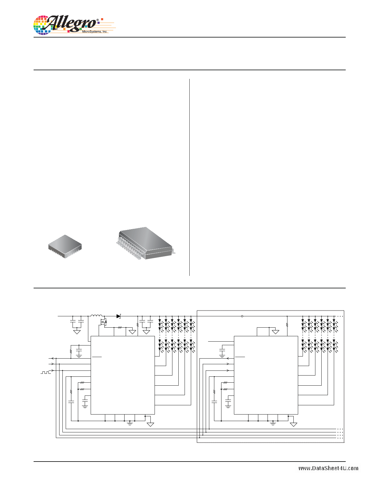
Typical Application Circuit
Fault
Enable
PWM
VBAT
8 to 24 V
C1 C2
L1
D1
Q1
RSC ROVP1
C3 C4
P
R1 C5
RFSET
RISET
Rz1
P
DRIVER SENSE1 SENSE2 OVP
VIN
VBIAS
FAULT
EN
PWM
COMP
FSET
ISET
VREG7V
A8512
(LB package)
Master
P
LED1
LED2
LED3
LED4
LED5
C6
Cz1
LED6
AGND AGND LGND LGND PGND
18 LEDs per string
P Control Bus
VOUT
ROVP2
VBAT
P
DRIVER SENSE1 SENSE2
VIN
VBIAS
OVP
C7
RFSET
RISET
Rz2
FAULT
EN
PWM
COMP
FSET
ISET
VREG7V
A8512
(LB package)
Slave A
LED1
LED2
LED3
LED4
LED5
C8
Cz2
LED6
AGND AGND LGND LGND PGND
P
18 LEDs per string
To additional slaves
Figure 1. Typical application circuit for single IC operation, and (in dotted box) master/slave multiple IC operation.
A8512L-DS
1 page 
A8512
www.DataSheet4U.com
LED Backlight Driver for Medium/Large Displays
ELECTRICAL CHARACTERISTICS Valid at VIN = 12 V; TA = 25°C, RFSET = 52 kΩ, RISET = 12.4 kΩ, except indicates
specifications guaranteed over the full operating temperature range with TA = TJ , unless otherwise noted
Characteristics
Symbol
Test Conditions
Min. Typ.1 Max.
Input Voltage Range
Internal Bias Voltage Range
Internal Gate Driver Voltage
Undervoltage Lockout Threshold for VIN
Undervoltage Lockout Hysteresis for VIN
VIN
VBIAS
VDRIVER
VUVLO
VUVLOHYS
VIN ≥ 10 V
VIN falling
Switching at no load
8–
4.75 –
6.5 –
5.7 6.5
– 0.55
–7
24
5.5
8
6.8
–
–
Supply Current2
IVIN Shutdown, EN = VIL, TA = 25°C
Standby, EN = VIH, PWM = VIL, soft start
completed
– 0.1 1
–23
Boost Controller
Switching Frequency
Minimum Switch Off-Time
Minimum Switch On-Time
Logic Input Levels (EN and PWM pins)
fSW
toff(min)
ton(min)
Driver output
Driver output
0.8 1 1.25
– 72 –
– 72 –
Input Voltage Level Low
Input Voltage Level High
Input Leakage Current2
Error Amplifier
VIL
VIH
IIN EN = PWM = 5 V
– – 0.4
1.5 –
–
– 100 –
COMP Pin Source Current
COMP Pin Sink Current
COMP Pin Pull-Down Resistance
Driver Section
IEA(src)
IEA(snk)
RCOMPPD
VCOMP = 1.5 V
VCOMP = 1.5 V
¯F¯¯A¯¯U¯¯L¯¯T¯ = 1
– 160 –
– 20 –
– 1000 –
Peak Source Current5
Peak Sink Current5
High Side Gate Drive On Resistance
Low Side Gate Drive On Resistance
Sense Overcurrent Threshold Voltage
LED Current Sinks
Ipk(src)
Ipk(snk)
RDS(on)H
RDS(on)L
VSEN
Measured at VDRIVER = 0 V
Measured at VDRIVER = VREG7V
Measured at VDRIVER = VREG7V / 2
Measured at VDRIVER = VREG7V / 2
VSENSE1 – VSENSE2
–2–
–2–
–4–
–3–
80 95 110
LEDx Pin Regulation Voltage
ISET to ILEDx Current Gain
ISET Pin Voltage
ISET Allowable Current Range2
VLEDx
AISET
VISET
ISET
ILED = 80 mA
ISET = 100 μA
– 1.4 –
– 640 –
– 1.235 –
41 – 125
Unit
V
V
V
V
V
mA
μA
mA
MHz
ns
ns
V
V
μA
μA
μA
kΩ
A
A
Ω
Ω
mV
V
A/A
V
μA
Continued on the next page…
Allegro MicroSystems, Inc.
115 Northeast Cutoff
Worcester, Massachusetts 01615-0036 U.S.A.
1.508.853.5000; www.allegromicro.com
5
5 Page 
A8512
www.DataSheet4U.com
LED Backlight Driver for Medium/Large Displays
Functional Description
Overview The A8512 is a multi-output WLED/RGB control-
ler for backlighting medium-size displays. It has an integrated
gate driver for driving an external N-channel boost MOSFET.
The gate driver voltage is regulated at 7 V, which allows a wide
selection of power MOSFET (in contrast to being limited to
logic-level MOSFETs when using a 5 V gate driver). The boost
controller operates in fixed-frequency current-mode control. The
switching frequency can be set in the range from 300 kHz to
1 MHz, by an external resistor, RFSET, connected between FSET
and ground.
The external MOSFET switch is protected by pulse-by-pulse cur-
rent limiting. The current limit is independent of duty cycle, and
is set using an external sense resistor, RSC.
The A8512 has six well-matched current sinks that provide regu-
lated current through the LEDs for uniform display brightness.
The boost converter is controlled by monitoring all LEDx pins
simultaneously and continuously.
Multiple A8512 can be connected in parallel, for applications
that require more than six LED strings. One master controller is
in charge of the boost converter stage, while other slave control-
lers act as LED current sinks only. The converter output voltage
will be boosted to a level just sufficient for all LED currents to be
within regulation.
Up to six A8512s (1 master + 5 slaves) can be connected in
parallel, which allows up to 36 LED strings to be powered by just
one boost converter. The maximum number of LEDs within each
string is limited only by the voltage ratings of the external power
components (MOSFET, diode, and capacitors).
LED Current Setting The maximum LED current can be set,
at up to 80 mA/channel, through the ISET pin. Connect a resistor,
RISET , between this pin and ground to set the reference current
level, ISET . The value of ISET (mA) is determined by:
ISET = 1.235 / RISET (kΩ) .
(1)
The resulting current is multiplied internally with a gain of 640
and mirrored on all enabled LEDx pins. This sets the maximum
current through each LEDx, referred as the 100% Current. The
LEDx current can be reduced from the 100% Current value by
applying an external PWM signal on the PWM pin. Conversely,
we can calculate RISET according to the LED current required:
RISET = ( 1.235 / ILED ) × 640 .
(2)
Boost Switching Frequency Setting Connect an external
resistor between the FSET pin and GND, to set boost switching
frequency, fSW . The value of fSW (MHz) is determined by:
fSW = 52 / RFSET ,
(3)
where fSW is in MHz and RFSET is in kΩ. The typical range of
RFSET is approximately 51 to 174 kΩ, which corresponds to
1 MHz to 300 kHz.
Enable The IC turns on when a high signal is applied on the EN
pin, and turns off when this pin is pulled low. The LED current
sinks are turned on when both the EN and the PWM inputs are high.
Channel Selection The A8512 can be used to drive 1 to 6 LED
channels. During startup, the IC detects LED sink pins which are
shorted to ground, and disables the corresponding LED channel.
Therefore, any unused LED pins must be connected to ground,
otherwise the IC will go into overvoltage protection fault during
startup. LED pins can be paralleled together for higher cur-
rent. For example for a 3 parallel string configuration, connect
LED1-2, LED3-4, and LED5-6 together to deliver up to 160 mA
per LED.
PWM Dimming The A8512 has a very wide range for PWM
signal input. It can accept a PWM signal from 100 Hz to 5 kHz.
When a PWM high signal is applied, the LEDx pins sink
100% Current. When the PWM signal is low, the LED sinks
turn off.
Referring to figure 13, there is a ramp-up delay between when
the PWM signal is applied and when the current reaches the
90% level. To improve current dimming linearity for PWM pulse
widths less than 100 μs, increase the applied PWM pulse-width
by 3 to 5 μs to compensate for this delay.
PWM
tD
ILED
Figure 13. Propagation delay from the PWM signal rising edge to ILEDx
reaching the 90% level
Allegro MicroSystems, Inc.
115 Northeast Cutoff
Worcester, Massachusetts 01615-0036 U.S.A.
1.508.853.5000; www.allegromicro.com
11
11 Page | ||
| Páginas | Total 16 Páginas | |
| PDF Descargar | [ Datasheet A8512.PDF ] | |
Hoja de datos destacado
| Número de pieza | Descripción | Fabricantes |
| A8510 | High Efficiency Fault Tolerant LED Driver | Allegro |
| A8512 | LED Backlight Driver | Allegro Micro Systems |
| A8514 | High Efficiency Fault Tolerant LED Driver | Allegro |
| Número de pieza | Descripción | Fabricantes |
| SLA6805M | High Voltage 3 phase Motor Driver IC. |
Sanken |
| SDC1742 | 12- and 14-Bit Hybrid Synchro / Resolver-to-Digital Converters. |
Analog Devices |
|
DataSheet.es es una pagina web que funciona como un repositorio de manuales o hoja de datos de muchos de los productos más populares, |
| DataSheet.es | 2020 | Privacy Policy | Contacto | Buscar |