|
|
|
PDF MAX6963 Data sheet ( Hoja de datos )
| Número de pieza | MAX6963 | |
| Descripción | 4-Wire Serially Interfaced 8 x 8 Matrix Graphic LED Drivers | |
| Fabricantes | Maxim Integrated Products | |
| Logotipo | ||
Hay una vista previa y un enlace de descarga de MAX6963 (archivo pdf) en la parte inferior de esta página. Total 30 Páginas | ||
|
No Preview Available !
MAX6960–MAX6963
4-Wire Serially Interfaced
8 x 8 Matrix Graphic LED Drivers
General Description
The MAX6960–MAX6963 are compact cathode-row dis-
play drivers that interface microprocessors to 8 x 8 dot-
matrix red, green, and yellow (R,G,Y) LED displays
through a high-speed 4-wire serial interface.
The MAX6960–MAX6963 drive two monocolor 8 x 8
matrix displays, or a single RGY 8 x 8 matrix display with
no external components. The driver can also be used
with external pass transistors to control red, green, blue
(RGB) and other displays at higher currents and voltages.
The MAX6960–MAX6963 feature open- and short-circuit
LED detection, and provide both analog and digital tile
segment current calibration to allow 8 x 8 displays from
different batches to be compensated or color matched.
A local 3-wire bus synchronizes multiple interconnected
MAX6960–MAX6963s and automatically allocates memory
map addresses to suit the user’s display-panel
architecture.
The MAX6960–MAX6963s’ 4-wire interface connects mul-
tiple drivers, with display memory mapping shared and
allocated among the drivers. A single global write opera-
tion can send a command to all MAX6960s in a panel.
The MAX6963 drives monocolor displays with two-step
intensity control. The MAX6962 drives monocolor displays
with two-step or four-step intensity control. The MAX6961
drives monocolor or RGY displays with two-step intensity
control. The MAX6960 drives monocolor or RGY displays
with two-step or four-step intensity control.
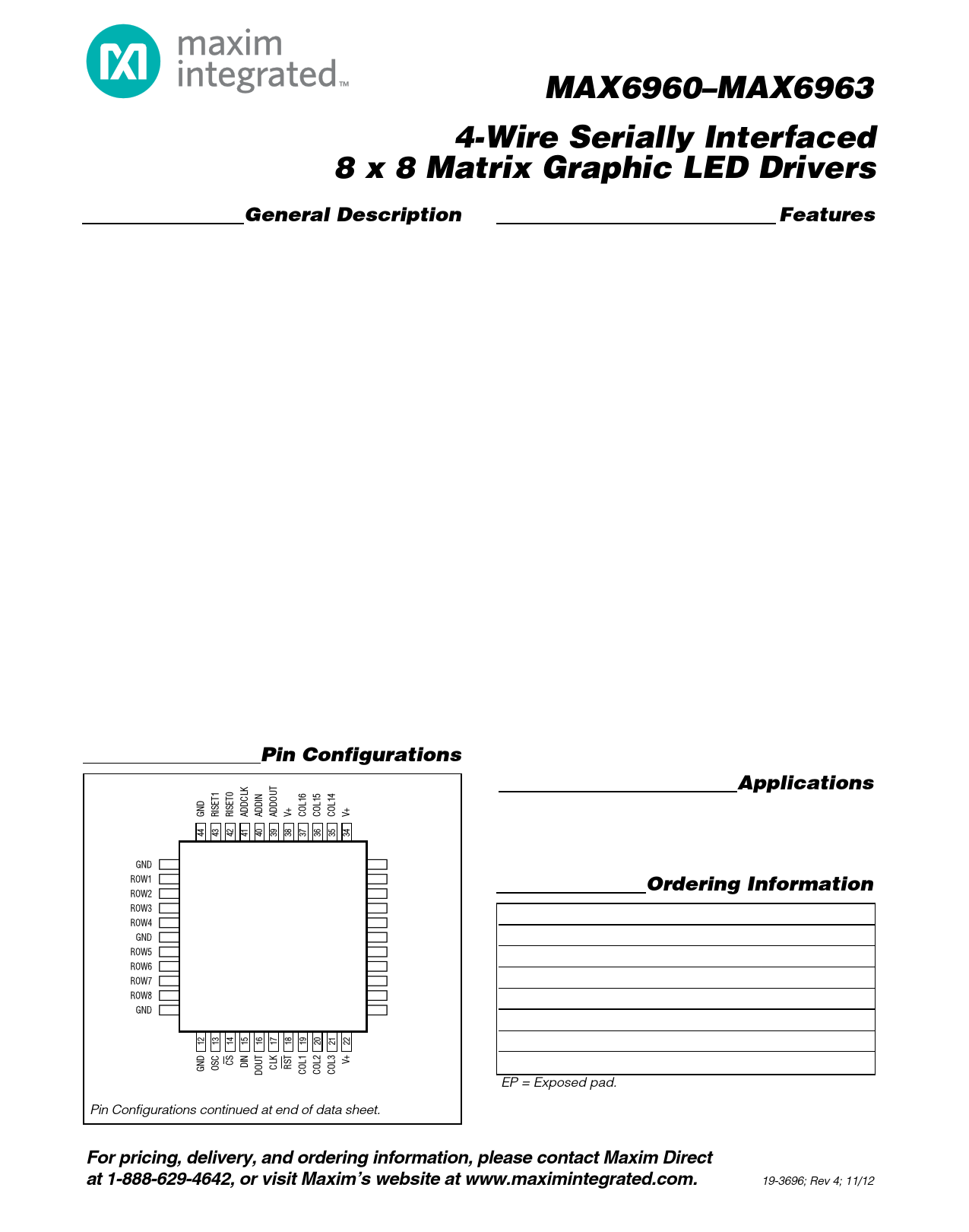
Pin Configurations
TOP VIEW
1 33 COL13
2 32 COL12
3 31 COL11
4 30 COL10
5 MAX6960-MAX6963 29 COL9
6 28 V+
7 27 COL8
8 26 COL7
9 25 COL6
10 24 COL5
11 23 COL4
MQFP
Pin Configurations continued at end of data sheet.
Features
o 2.7V to 3.6V Operation
o High-Speed 20MHz Serial Interface
o Trimmed 40mA or 20mA Peak Segment Current
o Directly Drives Either Two Monocolor or One RGY
Cathode-Row 8 x 8 Matrix Displays
o Analog Digit-by-Digit Segment Current Calibration
o Digital Digit-by-Digit Segment Current Calibration
o 256-Step Panel Intensity Control (All Drivers)
o Four Steps per Color Pixel-Level Intensity Control
o Open/Short LED Detection
o Burst White to Display Memory Planes
o Global Command Access All Devices
o Can Control RGB Panels or Higher
Current/Voltage Panels with External Pass
Transistors
o Multiple Display Data Planes Ease Animation
o Automatic Plane Switching from 63 Planes per
Second to One Plane Every 63s, with Interrupt
o Slew-Rate-Limited Segment Drivers for Lower EMI
o Driver Switching Timing Can Be Spread Between
Multiple Drivers to Flatten Power-Supply Peak
Demand
o Low-Power Shutdown with Full Data Retention
o -40°C to +125°C Temperature Range
Message Boards
Gaming Machines
Applications
Industrial Controls
Audio/Video Equipment
Ordering Information
PART
MAX6960ATH
MAX6961AMH
MAX6961ATH
MAX6962AMH
MAX6962ATH
MAX6963AMH
MAX6963ATH
*EP = Exposed pad.
TEMP RANGE
-40°C to +125°C
-40°C to +125°C
-40°C to +125°C
-40°C to +125°C
-40°C to +125°C
-40°C to +125°C
-40°C to +125°C
PIN-PACKAGE
44 TQFN-EP*
44 MQFP
44 TQFN-EP*
44 MQFP
44 TQFN-EP*
44 MQFP
44 TQFN-EP*
For pricing, delivery, and ordering information, please contact Maxim Direct
at 1-888-629-4642, or visit Maxim’s website at www.maximintegrated.com.
19-3696; Rev 4; 11/12
1 page 
MAX6960–MAX6963
4-Wire Serially Interfaced
8 x 8 Matrix Graphic LED Drivers
Pin Description
PIN
MQFP TQFN
1, 6, 11, 1, 6, 11,
12, 44 12, 44
NAME
GND
Ground
FUNCTION
2–5, 7–10 2–5, 7–10 ROW1–ROW8 LED Cathode Drivers. ROW1 to ROW8 outputs sink current from the display's cathode rows.
13
14
15
16
17
18
19, 20,
21,
23–27,
29–33,
35, 36,
37
22, 28,
34, 38
39
40
41
42
13
14
15
16
17
18
19, 20,
21,
23–27,
29–33,
35, 36,
37
22, 28,
34, 38
39
40
41
42
OSC
CS
DIN
DOUT
CLK
RST
Multiplex Clock Input. Drive OSC with a 1MHz to 8.5MHz CMOS clock.
Chip-Select Input. Serial data is loaded into the shift register when CS is low. Data is
loaded into the data latch on CS's rising edge.
Serial-Data Input. Data from DIN loads into the internal shift register on CLK's rising edge.
Serial-Data Output. The output is tri-state.
Serial-Clock Input. On CLK's rising edge data shifts into the internal shift register.
Reset Input. Hold RST low until at least 50ms after all interconnected MAX6960s are
powered up.
LED Anode Drivers. COL1 to COL16 outputs source current into the display's anode
COL1–COL16 columns.
V+
ADDOUT
ADDIN
ADDCLK
RISET0
Positive Supply Voltage. Bypass V+ to GND with a single 47µF bulk capacitor per chip
plus a 0.1µF ceramic capacitor per V+.
Address-Data Output. Connect ADDOUT to ADDIN of the next MAX6960. Use ADDOUT of
the last MAX6960 as a plane change interrupt output.
Address-Data Input. For first MAX6960, connect ADDIN to V+. For other MAX6960s,
connect ADDIN to ADDOUT of the preceding MAX6960.
Address-Clock Input/Output. Connect ADDCLK of all MAX6960 drivers together, ensuring
that only one MAX6960's ADDIN input is connected to V+.
Digit 0 Current Setting. Connect RISET0 to GND to program all of digit 0's segment
currents to 40mA. Leave RISET0 open circuit to program all of digit 0's segment currents
to 20mA. Connect RISET0 to GND through a fixed or variable resistor to adjust all of digit
0's segment currents between 20mA and 40mA.
43 43
— EP
RISET1
EP
Digit 1 Current Setting. Connect RISET1 to GND to program all of digit 1's segment
currents to 40mA. Leave RISET1 open circuit to program all of digit 1's segment currents
to 20mA. Connect RISET1 to GND through a fixed or variable resistor to adjust all of digit
1's segment currents between 20mA and 40mA.
Exposed Pad on Package Underside. Connect to GND.
Maxim Integrated
5
5 Page 
MAX6960–MAX6963
4-Wire Serially Interfaced
8 x 8 Matrix Graphic LED Drivers
Table 7. Register Addressing Modes
DATA FORMAT
8-, 16-, OR 24-BIT DATA PACKET SENT TO MAX6960
8-bit indirect display
memory addressing.
Address is global display
indirect address (14 bits)
stored as {MSB, LSB} in
{register 0x0A, register
0x09}.
16-bit device addressing.
Factory reserved; do not
write to this address.
24-bit direct display
memory addressing
(monocolor 1 bit per
pixel).
24-bit direct display
memory addressing
(RGY 1 bit per pixel).
24-bit direct display
memory addressing
(monocolor 2 bits per
pixel).
24-bit direct display
memory addressing
(RGY 2 bits per pixel).
R/W
R/W
R/W
R/W
—
—
—
R/W AI L/G 0
1
4-bit
address
X
Planes 12-bit addressing across 256 drivers,
0, 1, 2, 3 4096 x 8 red pixels
X
Planes
0, 1, 2, 3
12-bit addressing across 256 drivers,
2048 x 8 red pixels, and
2048 x 8 green pixels
X Planes 13-bit addressing across 256 drivers,
0, 1 4096 x 4 red pixels
X
Planes
0, 1
13-bit addressing across 256 drivers,
4096 x 4 red pixels, and
4096 x 4 green pixels
8 bits of display memory
8 bits of driver register data
—
8 bits of display memory
(1 bit per pixel)
8 bits of display memory
(1 bit per pixel)
8 bits of display memory
(2 bits per pixel)
8 bits of display memory
(2 bits per pixel)
8-Bit Transmissions
Eight-bit transmissions are write-only, data-only
accesses that write data to the display memory indi-
rected by the global display indirect address register
(Figure 6). The global display indirect address register
autoincrements after the write access. Eight-bit trans-
missions provide the quickest method of updating a
plane of display memory of the MAX6960. It is the most
suitable display update method if the host system
builds an image in local memory, and then dumps the
image into a display plane of the MAX6960.
16-Bit Transmissions
Sixteen-bit transmissions are read/write, command-
and-data accesses to the MAX6960’s configuration
registers (Figure 7). A write can generally be global
(updates all MAX6960s on the 4-wire bus with the same
Maxim Integrated
data) or specific (updates just the MAX6960 indirected
by the global driver indirect address register). Note:
The global driver indirect address register selects a
specific MAX6960. This is not the same as the glob-
al display indirect address register, which points to
display memory that could be in any MAX6960. A
16-bit read is always indirected through the global dri-
ver indirect address register to select only one
MAX6960 to respond. When a read or write is indirect-
ed through the global driver indirect address register,
the 16-bit command can choose whether the global dri-
ver indirect address is autoincremented after the com-
mand has been executed. This allows the host to set up
one or more registers in consecutive MAX6960s with
the display indirect address, autoincrementing only
when required.
11
11 Page | ||
| Páginas | Total 30 Páginas | |
| PDF Descargar | [ Datasheet MAX6963.PDF ] | |
Hoja de datos destacado
| Número de pieza | Descripción | Fabricantes |
| MAX696 | Microprocessor Supervisory Circuits | Maxim Integrated |
| MAX6960 | 4-Wire Serially Interfaced 8 x 8 Matrix Graphic LED Drivers | Maxim Integrated Products |
| MAX6961 | 4-Wire Serially Interfaced 8 x 8 Matrix Graphic LED Drivers | Maxim Integrated Products |
| MAX6962 | 4-Wire Serially Interfaced 8 x 8 Matrix Graphic LED Drivers | Maxim Integrated Products |
| Número de pieza | Descripción | Fabricantes |
| SLA6805M | High Voltage 3 phase Motor Driver IC. |
Sanken |
| SDC1742 | 12- and 14-Bit Hybrid Synchro / Resolver-to-Digital Converters. |
Analog Devices |
|
DataSheet.es es una pagina web que funciona como un repositorio de manuales o hoja de datos de muchos de los productos más populares, |
| DataSheet.es | 2020 | Privacy Policy | Contacto | Buscar |