|
|
|
PDF GS001 Data sheet ( Hoja de datos )
| Número de pieza | GS001 | |
| Descripción | Getting Started | |
| Fabricantes | Microchip Technology | |
| Logotipo | ||
Hay una vista previa y un enlace de descarga de GS001 (archivo pdf) en la parte inferior de esta página. Total 8 Páginas | ||
|
No Preview Available !
GS001
Getting Started with BLDC Motors and dsPIC30F Devices
Author: Stan D’Souza
Microchip Technology Inc.
INTRODUCTION
As a means of reducing high energy and maintenance
costs in motor control applications, BLDC motors are
seeing a resurgence in applications where efficiency
and reliability are important. The dsPIC30F motor con-
trol devices are ideally suited to drive and control a
wide range of BLDC motor types, in a large number of
applications. Microchip has developed a number of
solutions using the dsPIC30F and BLDC motors. This
document will help you select an appropriate solution
for your BLDC motor application.
BLDC MOTOR BASICS
DC brush motors have a permanent magnet on the
stator with the motor winding on the rotor. During rota-
tion, the current in the windings is reversed using
mechanical carbon brushes and a commutator located
on the rotor. The BLDC motor has permanent magnets
on the rotor with the electrical windings on the stator.
The first obvious advantage of the BLDC motor is the
elimination of the mechanical commutator and
brushes, which significantly improves mechanical
www.DataSheeraetl4slUioa.bcoiglimtiyv.eThriesecomtomustpaatorkrinagn,d
brushes in DC
so eliminating
motors
these
components means that BLDC motors can operate in a
harsh environment. The I2R heat losses in the windings
of a BLDC motor are now on the stator and can be
dissipated very easily. Consequently, efficiency of the
BLDC motor is vastly improved.
There are, however, some challenges when spinning a
BLDC motor. Firstly, a revolving electrical field has to
be created in the windings, which also has to be well
aligned with the magnetic field on the rotor. The
efficiency of the BLDC motor depends largely on the
alignment of the revolving electrical field to the
magnetic field on the rotor. To sense the magnetic field,
Hall sensors are normally used. Based on the signal
presented by the Hall sensors, the windings are appro-
priately excited. As the speed of the rotor increases,
however, there is a certain amount of lag between the
voltage excitation and the current effect on the
windings due to the inductance of the windings. To
overcome this lag, the voltage is initiated a little in
advance. This phenomenon is known as phase
advance and is implemented mainly in software at high
speeds of rotation. The result of phase advance is
better efficiency in the BLDC motor operation.
Sensored BLDC Motor Control
When driving a BLDC motor, it is important to know the
position of the magnetic rotor with reference to the
stator. Most commonly, Hall effect sensors are used to
generate feedback on the rotor position. This type of
control is called sensored BLDC motor control. Most
BLDC motors have three windings. Based on the
position of the magnetic rotor, two windings are ener-
gized at a given time with each phase conducting for
120 electrical revolution degrees, resulting in six
distinct combinations of energization. This type of drive
is called “trapezoidal” or “six-step commutation”.
SIX-STEP COMMUTATION
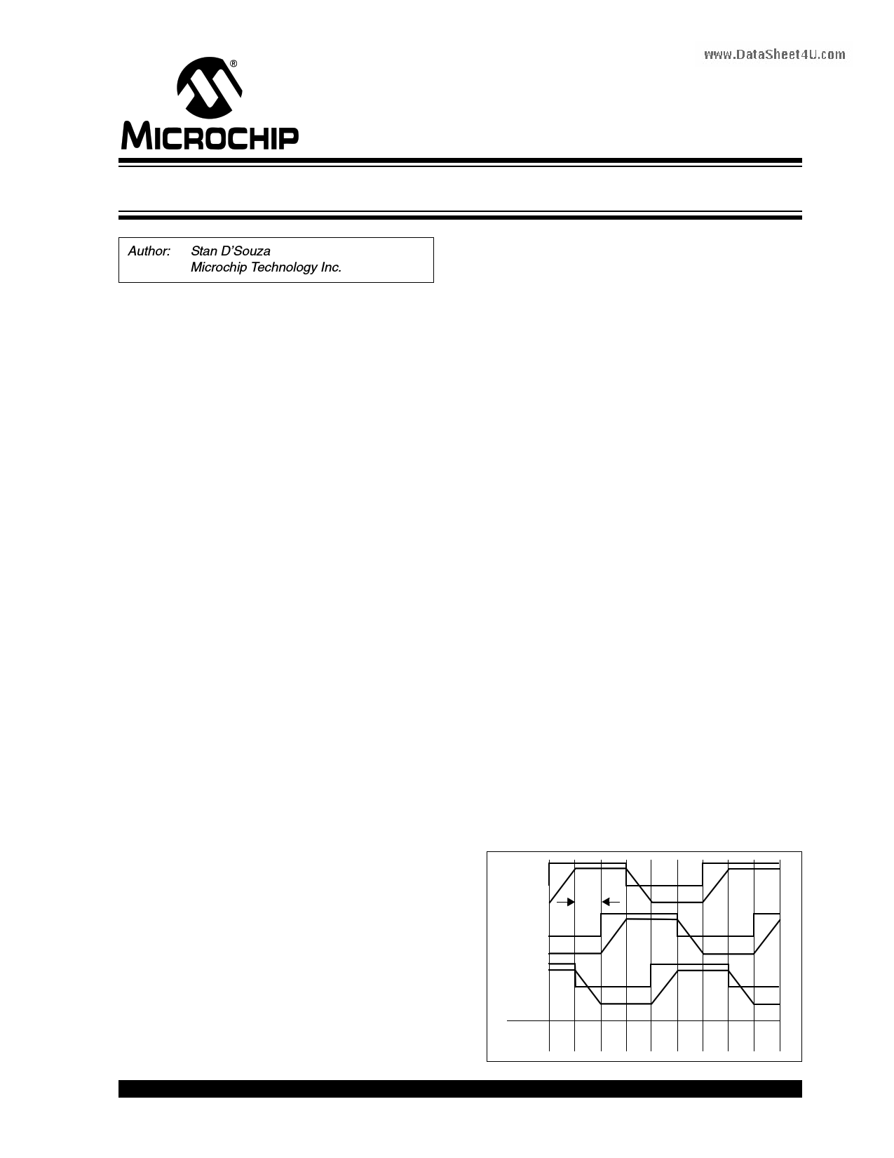
Figure 1 depicts a typical six-step commutation
scheme with the Hall sensor output overlay. Six-step
commutation offers a simple, yet efficient, method of
driving a BLDC motor. Hall A (HA), Hall B (HB) and Hall
C (HC) sense the position of the rotor with respect to
the windings, R, Y and B. Depending on the Hall sensor
reading from 1 to 6, an appropriate pair of windings is
driven high and low with the third winding not driven.
Each 360 degree electrical cycle is broken down to six
60 degree electrical sectors, in which one winding is
driven high, a second is driven low and the third is not
driven. Example: In Hall position 6 or sector 1, the R
winding is driven high while the B winding is driven low
and the Y winding is not driven. By reading the Hall
sensors, the six-step commutation algorithm can very
easily be implemented in software.
FIGURE 1:
TYPICAL SIX-STEP
COMMUTATION
HA
R 60°
HB
Y
HC
B
Sector 5 0 1 2 3 4 5 0 1
Hall 5 4 6 2 3 1 5 4 6
© 2005 Microchip Technology Inc.
DS93001A-page 1
1 page 
FIGURE 5:
dsPICDEM™ MC1H 3-
PHASE HV MODULE
GS153
FIGURE 6:
dsPICDEM™ MC1L 3-PHASE
LV MODULE
dsPICDEM MC1H 3-Phase High-Voltage
Power Module
The high-voltage module (Figure 5) connects to an
MC1 board to form a high-voltage BLDC motor control
system. The dsPICDEM MC1H 3-Phase High-Voltage
Power module offers high-voltage isolation, as well as
Fault, overcurrent and overvoltage protection. Each
phase is monitored with fast current sensors and a
robust latching network to disable the outputs in case
any Fault condition occurs. This protection is neces-
sary during code development and prevents accidental
destruction of the drive circuitry due to inadvertent
software issues.
The high-voltage module rectifies a single-phase wall
input voltage of 110 VAC to generate a DC bus voltage
of 165 VDC. Alternatively, it can also rectify an input
www.DataSheewt4aUll.cvoomltage of 220 VAC to get a DC bus voltage of
330 VDC. This DC bus voltage is then converted to
drive a 3-phase motor.
The hardware can be used to drive ACIM and BLDC
motors. For complete details on the features and
capabilities of this module, refer to the “dsPICDEM™
MC1H 3-Phase High-Voltage Power Module User’s
Guide” (DS70096).
dsPICDEM MC1L 3-Phase Low-Voltage
Power Module
The low-voltage module (Figure 6) connects to an MC1
board to form a low-voltage BLDC motor control
system. The dsPICDEM MC1L 3-Phase Low-Voltage
Power module offers voltage isolation, along with Fault,
overcurrent and overvoltage protection. Each phase is
monitored with fast current sensors and a robust latch-
ing network to disable the outputs in case any Fault
condition occurs. This protection is necessary during
code development and prevents accidental destruction
of the drive circuitry due to inadvertent software issues.
DC voltage is supplied externally from a power supply.
This DC bus voltage is then converted to drive a 3-phase
motor.
The hardware can drive 3-phase low-voltage BLDC
motors. For more details on the features and cap-
abilities of this module, refer to the “dsPICDEM™
MC1L 3-Phase Low-Voltage Power Module User’s
Guide (DS70097).
© 2005 Microchip Technology Inc.
DS93001A-page 5
5 Page | ||
| Páginas | Total 8 Páginas | |
| PDF Descargar | [ Datasheet GS001.PDF ] | |
Hoja de datos destacado
| Número de pieza | Descripción | Fabricantes |
| GS001 | Getting Started | Microchip Technology |
| Número de pieza | Descripción | Fabricantes |
| SLA6805M | High Voltage 3 phase Motor Driver IC. |
Sanken |
| SDC1742 | 12- and 14-Bit Hybrid Synchro / Resolver-to-Digital Converters. |
Analog Devices |
|
DataSheet.es es una pagina web que funciona como un repositorio de manuales o hoja de datos de muchos de los productos más populares, |
| DataSheet.es | 2020 | Privacy Policy | Contacto | Buscar |