|
|
|
PDF IRLBA1304 Data sheet ( Hoja de datos )
| Número de pieza | IRLBA1304 | |
| Descripción | Power MOSFET ( Transistor ) | |
| Fabricantes | International Rectifier | |
| Logotipo | ||
Hay una vista previa y un enlace de descarga de IRLBA1304 (archivo pdf) en la parte inferior de esta página. Total 8 Páginas | ||
|
No Preview Available !
www.datasheet4u.com
l Logic-Level Gate Drive
l Ultra Low On-Resistance
l Same outline as TO-220
l 50% greater current in typ.
application conditions vs. TO-220
l Fully Avalanche Rated
q Purchase IRLBA1304/P for solder plated option.
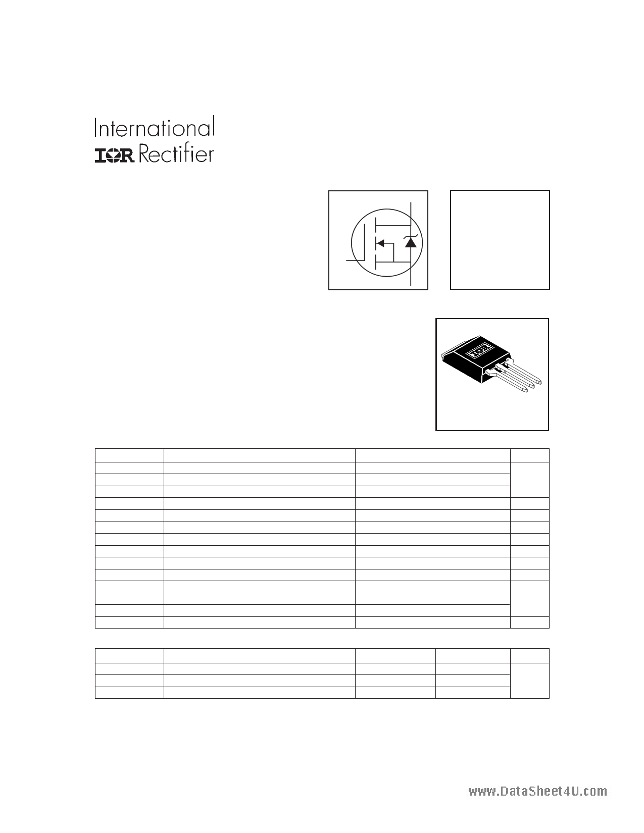
G
PD- 91842A
IRLBA1304
HEXFET® Power MOSFET
D VDSS = 40V
RDS(on) = 0.004Ω
ID = 185A
S
Description
The HEXFET® is the most popular power MOSFET in the world.
This particular HEXFET® is in the Super220TM and has the same outline and
pinout as the industry standard TO-220. It has increased current handling
capability over both the TO-220 and the much larger TO-247 package. This
makes it ideal to reduce component count in multiparalled TO-220 applications,
reduce system power dissipation, upgrade existing designs or have TO-247
performance in a TO-220 outline. This package has also been designed to meet
automotive qualification standard Q101.
Super - 220
Absolute Maximum Ratings
ID @ TC = 25°C
ID @ TC = 100°C
IDM
PD @TC = 25°C
VGS
EAS
IAR
EAR
dv/dt
TJ
TSTG
Parameter
Continuous Drain Current, VGS @ 10V
Continuous Drain Current, VGS @ 10V
Pulsed Drain Current
Power Dissipation
Linear Derating Factor
Gate-to-Source Voltage
Single Pulse Avalanche Energy
Avalanche Current
Repetitive Avalanche Energy
Peak Diode Recovery dv/dt
Operating Junction and
Storage Temperature Range
Soldering Temperature, for 10 seconds
Recommended clip force
Max.
185, pkg limited to 95A*
130, pkg limited to 95A*
740
300
2.0
± 16
1160
100
30
5.0
-55 to + 175
300 (1.6mm from case )
20
Units
A
W
W/°C
V
mJ
A
mJ
V/ns
°C
N
Thermal Resistance
RθJC
RθCS
RθJA
Parameter
Junction-to-Case
Case-to-Sink, Flat, Greased Surface
Junction-to-Ambient
Typ.
–––
0.5
–––
Max.
0.5
–––
58
Units
°C/W
* Current capability in normal application, see Fig.9.
www.irf.com
1
9/14/99
1 page 
www.datasheet4u.com
200
160
LIMITED BY PACKAGE
120
80
40
0
25 50 75 100 125 150 175
TC , Case Temperature ( °C)
Fig 9. Maximum Drain Current Vs.
Case Temperature
IRLBA1304
VDS
VGS
RG
RD
D.U.T.
4.5V
Pulse Width ≤ 1 µs
Duty Factor ≤ 0.1 %
+-VDD
Fig 10a. Switching Time Test Circuit
VDS
90%
10%
VGS
td(on) tr
td(off) tf
Fig 10b. Switching Time Waveforms
1
D = 0.50
0.1 0.20
0.10
0.05
0.02
0.01
0.01
0.001
0.00001
SINGLE PULSE
(THERMAL RESPONSE)
PDM
t1
t2
Notes:
1. Duty factor D = t1 / t 2
2. Peak T J = P DM x Z thJC + TC
0.0001
0.001
0.01
t1, Rectangular Pulse Duration (sec)
0.1
Fig 11. Maximum Effective Transient Thermal Impedance, Junction-to-Case
www.irf.com
1
5
5 Page | ||
| Páginas | Total 8 Páginas | |
| PDF Descargar | [ Datasheet IRLBA1304.PDF ] | |
Hoja de datos destacado
| Número de pieza | Descripción | Fabricantes |
| IRLBA1304 | Power MOSFET ( Transistor ) | International Rectifier |
| Número de pieza | Descripción | Fabricantes |
| SLA6805M | High Voltage 3 phase Motor Driver IC. |
Sanken |
| SDC1742 | 12- and 14-Bit Hybrid Synchro / Resolver-to-Digital Converters. |
Analog Devices |
|
DataSheet.es es una pagina web que funciona como un repositorio de manuales o hoja de datos de muchos de los productos más populares, |
| DataSheet.es | 2020 | Privacy Policy | Contacto | Buscar |