|
|
|
PDF MAX7315 Data sheet ( Hoja de datos )
| Número de pieza | MAX7315 | |
| Descripción | 8-Port I/O Expander | |
| Fabricantes | Maxim Integrated Products | |
| Logotipo | ||
1. MAX7315 Hay una vista previa y un enlace de descarga de MAX7315 (archivo pdf) en la parte inferior de esta página. Total 27 Páginas | ||
|
No Preview Available !
www.DataSheet4U.com
19-3056; Rev 0; 10/03
8-Port I/O Expander with LED Intensity
Control and Interrupt
General Description
The MAX7315 I2C™-/SMBus-compatible serial interfaced
peripheral provides microprocessors with 8 I/O ports.
Each I/O port can be individually configured as either an
open-drain current-sinking output rated at 50mA at 5.5V,
or a logic input with transition detection. A ninth port can
be used for transition detection interrupt or as a general-
purpose output. The outputs are capable of directly dri-
ving LEDs, or providing logic outputs with external
resistive pullup up to 5.5V.
PWM current drive is integrated with 8 bits of control.
Four bits are global control and apply to all LED outputs
to provide coarse adjustment of current from fully off to
fully on in 14 intensity steps. Each output then has indi-
vidual 4-bit control, which further divides the globally
set current into 16 more steps. Alternatively, the current
control can be configured as a single 8-bit control that
sets all outputs at once.
The MAX7315 is pin and software compatible with the
PCA9534 and PCA9554(A).
Each output has independent blink timing with two blink
phases. All LEDs can be individually set to be on or off
during either blink phase, or to ignore the blink control.
The blink period is controlled by a register.
The MAX7315 is controlled through the 2-wire I2C/SMBus
serial interface, and can be configured to one of 64 I2C
addresses.
Applications
LCD Backlights
LED Status Indication
Portable Equipment
Laptop Computers
Keypad Backlights
RGB LED Drivers
Cellular Phones
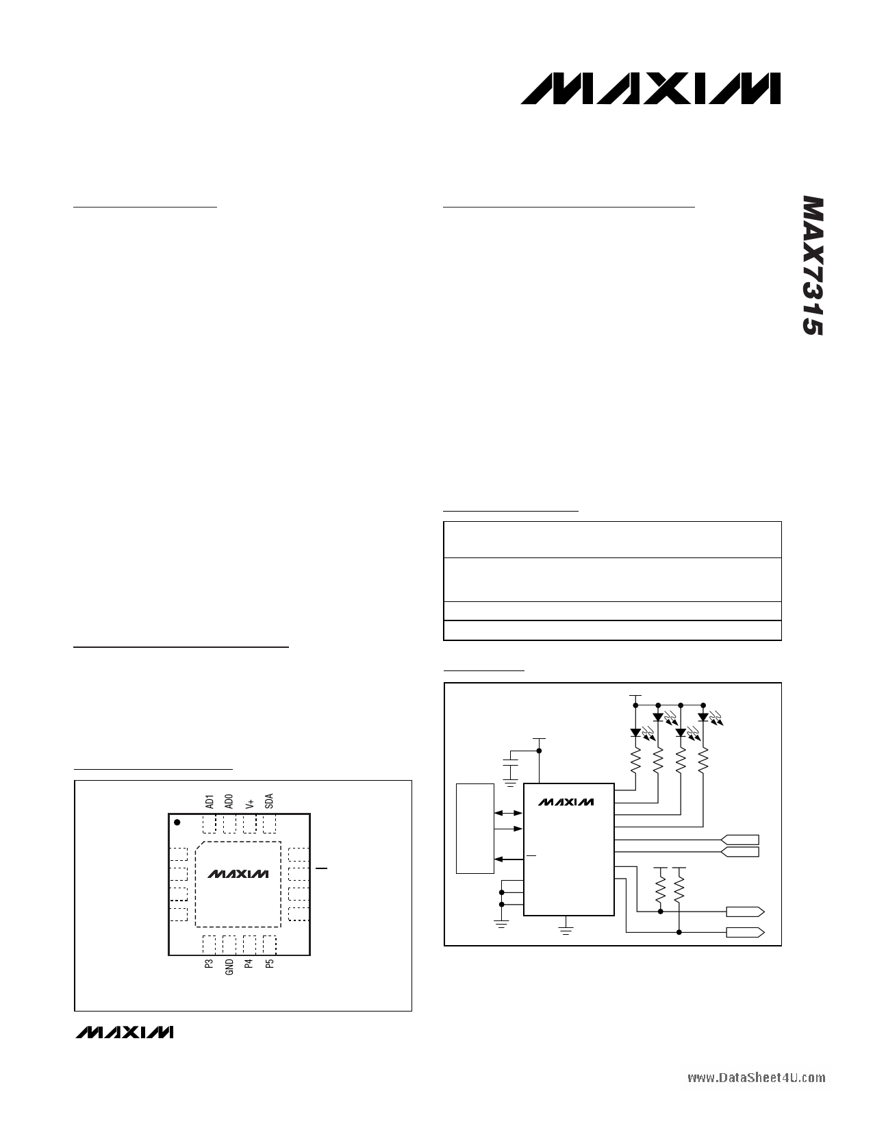
Pin Configurations
Features
o 400kbps, 2-Wire Serial Interface, 5.5V Tolerant
o 2V to 3.6V Operation
o Overall 8-Bit PWM LED Intensity Control
Global 16-Step Intensity Control
Plus Individual 16-Step Intensity Control
o Automatic Two-Phase LED Blinking
o 50mA Maximum Port Output Current
o Outputs Are 5.5V-Rated Open Drain
o Inputs Are Overvoltage Protected to 5.5V
o Transition Detection with Interrupt Output
o Low Standby Current (1.2µA typ; 3.3µA max)
o Tiny 3mm x 3mm, Thin QFN Package
o -40°C to +125°C Temperature Range
o All Ports Can Be Configured as Inputs or Outputs
Ordering Information
PART
TEMP RANGE
MAX7315ATE -40°C to +125°C
MAX7315AEE -40°C to +125°C
MAX7315AUE -40°C to +125°C
PIN-PACKAGE
16 Thin QFN
3mm x 3mm x
0.8mm
16 QSOP
16 TSSOP
TOP
MARK
AAU
—
—
Typical Application Circuit
5V
0.047µF
3.3V
TOP VIEW
16 15 14 13
AD2 1
P0 2
P1 3
P2 4
MAX7315ATE
12 SCL
11 INT/O8
10 P7
9 P6
µC
SDA
SCL
I/O
V+
SDA MAX7315
SCL
INT/O8
AD0
AD1
AD2
GND
P0
P1
P2
P3
P4
P5
P6
P7
5V 3.3V
INPUT 1
INPUT 2
OUTPUT1
OUTPUT2
5678
QFN
Pin Configurations continued at end of data sheet.
Purchase of I2C components of Maxim Integrated Products, Inc.,
or one of its sublicensed Associated Companies, conveys a
license under the Philips I2C Patent Rights to use these compo-
nents in an I2C system, provided that the system conforms to the
I2C Standard Specification as defined by Philips.
________________________________________________________________ Maxim Integrated Products 1
For pricing, delivery, and ordering information, please contact Maxim/Dallas Direct! at
1-888-629-4642, or visit Maxim’s website at www.maxim-ic.com.
1 page 
8-Port I/O Expander with LED Intensity
Control and Interrupt
(TA = +25°C, unless otherwise noted.)
PORT OUTPUT LOW VOLTAGE WITH 50mA
LOAD CURRENT vs. TEMPERATURE
0.6
0.5
0.4 V+ = 2V
V+ = 2.7V
0.3
0.2 V+ = 3.6V
0.1
0
-40 -25 -10 5 20 35 50 65 80 95 110 125
TEMPERATURE (°C)
Typical Operating Characteristics (continued)
PORT OUTPUT LOW VOLTAGE WITH 20mA
LOAD CURRENT vs. TEMPERATURE
0.6
ALL OUTPUTS LOADED
0.5
0.4
0.3 V+ = 2V
0.2
0.1 V+ = 2.7V V+ = 3.6V
0
-40 -25 -10 5 20 35 50 65 80 95 110 125
TEMPERATURE (°C)
PWM CLOCK FREQUENCY
vs. TEMPERATURE
1.050
1.025
1.000
V+ = 3.6V
0.975
0.950
V+ = 2.7V
V+ = 2V
0.925
0.900 NORMALIZED TO V+ = 3.3V, TA = +25°C
-40 -25 -10 5 20 35 50 65 80 95 110 125
TEMPERATURE (°C)
SCOPE SHOT OF 2 OUTPUT PORTS
MAX7315 toc07
MASTER INTENSITY SET TO 1/15
OUTPUT 1
2V/div
OUTPUT 1 INDIVIDUAL INTENSITY
SET TO 1/16
OUTPUT 2 INDIVIDUAL INTENSITY
SET TO 15/16
2ms/div
OUTPUT 2
2V/div
SCOPE SHOT OF 2 OUTPUT PORTS
MAX7315 toc08
MASTER INTENSITY SET TO 14/15
OUTPUT 1,
2V/div
OUTPUT 1 INDIVIDUAL INTENSITY
SET TO 1/16
0.35
0.30
0.25
0.20
OUTPUT 2 INDIVIDUAL INTENSITY
SET TO 14/15
2ms/div
0.15
OUTPUT 2,
2V/div
0.10
0.05
0
0
SINK CURRENT vs. VOL
V+ = 2V
V+ = 2.7V
V+ = 3.3V
V+ = 3.6V
ONLY ONE OUTPUT LOADED
10 20 30 40
SINK CURRENT (mA)
50
_______________________________________________________________________________________ 5
5 Page 
8-Port I/O Expander with LED Intensity
Control and Interrupt
COMMAND BYTE IS STORED ON RECEIPT OF
STOP CONDITION
ACKNOWLEDGE FROM MAX7315
D15 D14 D13 D12 D11 D10 D9 D8
S
SLAVE ADDRESS
0A
COMMAND BYTE
AP
Figure 7. Command Byte Received
R/W
ACKNOWLEDGE FROM MAX7315
HOW COMMAND BYTE AND DATA BYTE MAP INTO
MAX7315'S REGISTERS
ACKNOWLEDGE FROM MAX7315
ACKNOWLEDGE FROM MAX7315
D15 D14 D13 D12 D11 D10 D9 D8
ACKNOWLEDGE FROM MAX7315
D7 D6 D5 D4 D3 D2 D1 D0
S
SLAVE ADDRESS
0A
COMMAND BYTE
A
DATA BYTE
AP
R/W
1
BYTE
AUTOINCREMENT MEMORY ADDRESS
Figure 8. Command and Single Data Byte Received
HOW COMMAND BYTE AND DATA BYTE MAP INTO
MAX7315'S REGISTERS
ACKNOWLEDGE FROM MAX7315
ACKNOWLEDGE FROM MAX7315
D15 D14 D13 D12 D11 D10 D9 D8
ACKNOWLEDGE FROM MAX7315
D7 D6 D5 D4 D3 D2 D1 D0
S
SLAVE ADDRESS
0A
COMMAND BYTE
A
DATA BYTE
AP
N
R/W BYTES
AUTOINCREMENT MEMORY ADDRESS
Figure 9. n Data Bytes Received
Any bytes received after the command byte are data
bytes. The first data byte goes into the internal register
of the MAX7315 selected by the command byte (Figure
8). If multiple data bytes are transmitted before a STOP
condition is detected, these bytes are generally stored
in subsequent MAX7315 internal registers because the
command byte address autoincrements (Table 2). A
diagram of a write to the output ports registers (blink
phase 0 register or blink phase 1 register) is given in
Figure 10.
Message Format for Reading
The MAX7315 is read using the MAX7315’s internally
stored command byte as an address pointer the same
way the stored command byte is used as an address
pointer for a write. The pointer autoincrements after
each data byte is read using the same rules as for a
write (Table 2). Thus, a read is initiated by first configur-
ing the MAX7315’s command byte by performing a
write (Figure 7). The master can now read n consecu-
tive bytes from the MAX7315 with the first data byte
being read from the register addressed by the initial-
ized command byte. When performing read-after-write
verification, remember to reset the command byte’s
address because the stored command byte address
has been autoincremented after the write (Table 2). A
diagram of a read from the input ports register is shown
in Figure 10 reflecting the states of the ports.
Operation with Multiple Masters
If the MAX7315 is operated on a 2-wire interface with
multiple masters, a master reading the MAX7315 should
use a repeated start between the write, which sets the
MAX7315’s address pointer, and the read(s) that takes
the data from the location(s) (Table 2). This is because it
is possible for master 2 to take over the bus after master
1 has set up the MAX7315’s address pointer but before
master 1 has read the data. If master 2 subsequently
changes the MAX7315’s address pointer, then master
1’s delayed read can be from an unexpected location.
______________________________________________________________________________________ 11
11 Page | ||
| Páginas | Total 27 Páginas | |
| PDF Descargar | [ Datasheet MAX7315.PDF ] | |
Hoja de datos destacado
| Número de pieza | Descripción | Fabricantes |
| MAX731 | +5V/Adjustable Step-Up Current-Mode DC-DC Converters | Maxim Integrated |
| MAX731-MAX752 | +5V/Adjustable Step-Up Current-Mode DC-DC Converters | Maxim Integrated |
| MAX7310 | 2-Wire-Interfaced 8-Bit I/O Port Expander | Maxim Integrated Products |
| MAX7311 | 2-Wire-Interfaced 16-Bit I/O Port Expander | Maxim Integrated Products |
| Número de pieza | Descripción | Fabricantes |
| SLA6805M | High Voltage 3 phase Motor Driver IC. |
Sanken |
| SDC1742 | 12- and 14-Bit Hybrid Synchro / Resolver-to-Digital Converters. |
Analog Devices |
|
DataSheet.es es una pagina web que funciona como un repositorio de manuales o hoja de datos de muchos de los productos más populares, |
| DataSheet.es | 2020 | Privacy Policy | Contacto | Buscar |