|
|
|
PDF NTR4501N Data sheet ( Hoja de datos )
| Número de pieza | NTR4501N | |
| Descripción | Power MOSFET ( Transistor ) | |
| Fabricantes | ON Semiconductor | |
| Logotipo | ||
Hay una vista previa y un enlace de descarga de NTR4501N (archivo pdf) en la parte inferior de esta página. Total 6 Páginas | ||
|
No Preview Available !
www.DataSheet4U.com
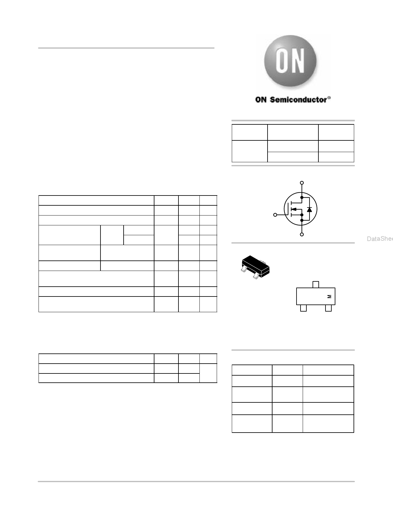
NTR4501N
Power MOSFET
20 V, 3.2 A, Single N−Channel, SOT−23
Features
• Leading Planar Technology for Low Gate Charge / Fast Switching
• 2.5 V Rated for Low Voltage Gate Drive
• SOT−23 Surface Mount for Small Footprint
• Pb−Free Package is Available
Applications
• Load/Power Switch for Portables
• Load/Power Switch for Computing
• DC−DC Conversion
MAXIMUM RATINGS (TJ= 25°C unless otherwise stated)
Parameter
Symbol Value Unit
Drain−to−Source Voltage
Gate−to−Source Voltage
Continuous Drain
Current (Note 1)
Steady State Power
Dissipation (Note 1)
Steady TA = 25°C
State
TA = 85°C
Steady State
VDSS
VGS
ID
20
±12
3.2
V
V
A
2.4 A
PD
1.25 W
DataSheet4U.com
Pulsed Drain Current
tp = 10 ms
Operating Junction and Storage Temperature
Continuous Source Current (Body Diode)
Lead Temperature for Soldering Purposes
(1/8” from case for 10 s)
IDM 10.0 A
TJ, −55 to °C
Tstg 150
IS 1.6 A
TL 260 °C
Maximum ratings are those values beyond which device damage can occur.
Maximum ratings applied to the device are individual stress limit values (not
normal operating conditions) and are not valid simultaneously. If these limits are
exceeded, device functional operation is not implied, damage may occur and
reliability may be affected.
THERMAL RESISTANCE RATINGS
Parameter
Symbol Max Unit
Junction−to−Ambient (Note 1)
RqJA
100 °C/W
Junction−to−Ambient (Note 2)
RqJA
300
1. Surface−mounted on FR4 board using 1 in sq pad size
(Cu area = 1.127 in sq [1 oz] including traces).
2. Surface−mounted on FR4 board using the minimum recommended pad size.
DataSheet4U.com
http://onsemi.com
V(BR)DSS
20 V
RDS(on) TYP
70 mW @ 4.5 V
85 mW @ 2.5 V
ID MAX
(Note 1)
3.6 A
3.1 A
N−Channel
D
G
S
3
1
2
SOT−23
CASE 318
STYLE 21
MARKING DIAGRAM/
PIN ASSIGNMENT
3
Drain
TR1
1
Gate
2
Source
TR1 = Specific Device Code
M = Date Code
ORDERING INFORMATION
Device
NTR4501NT1
Package
SOT−23
Shipping†
3000 / Tape & Reel
NTR4501NT1G SOT−23 3000 / Tape & Reel
(Pb−Free)
NTR4501NT3 SOT−23 10000 / Tape & Reel
NTR4501NT3G SOT−23 10000 / Tape & Reel
(Pb−Free)
†For information on tape and reel specifications,
including part orientation and tape sizes, please
refer to our Tape and Reel Packaging Specifications
Brochure, BRD8011/D.
DataShee
© Semiconductor Components Industries, LLC, 2005
March, 2005 − Rev. 4
1
Publication Order Number:
NTR4501N/D
1 page 
www.DataSheet4U.com
NTR4501N
PACKAGE DIMENSIONS
et4U.com
A
L
3
BS
12
VG
C
DH
K
SOT−23
(TO−236)
CASE 318−08
ISSUE AK
J
NOTES:
1. DIMENSIONING AND TOLERANCING PER ANSI
Y14.5M, 1982.
2. CONTROLLING DIMENSION: INCH.
3. MAXIMUM LEAD THICKNESS INCLUDES LEAD
FINISH THICKNESS. MINIMUM LEAD
THICKNESS IS THE MINIMUM THICKNESS OF
BASE MATERIAL.
4. 318−01 THRU −07 AND −09 OBSOLETE, NEW
STANDARD 318−08.
INCHES
DIM MIN
MAX
A 0.1102 0.1197
B 0.0472 0.0551
C 0.0350 0.0440
D 0.0150 0.0200
G 0.0701 0.0807
H 0.0005 0.0040
J 0.0034 0.0070
K 0.0140 0.0285
L 0.0350 0.0401
S 0.0830 0.1039
V 0.0177 0.0236
STYLE 21:
PIN 1. GATE
2. SOURCE
3. DRAIN
MILLIMETERS
MIN MAX
2.80
3.04
1.20
1.40
0.89
1.11
0.37
0.50
1.78
2.04
0.013 0.100
0.085 0.177
0.35
0.69
0.89
1.02
2.10
2.64
0.45
0.60
SOLDERING FOOTPRINT*
0.95
0.037
0.95
0.037
DataSheet4U.com
0.9
0.035
2.0
0.079
0.8
0.031
ǒ ǓSCALE 10:1
mm
inches
*For additional information on our Pb−Free strategy and soldering
details, please download the ON Semiconductor Soldering and
Mounting Techniques Reference Manual, SOLDERRM/D.
DataShee
DataSheet4U.com
http://onsemi.com
5
5 Page | ||
| Páginas | Total 6 Páginas | |
| PDF Descargar | [ Datasheet NTR4501N.PDF ] | |
Hoja de datos destacado
| Número de pieza | Descripción | Fabricantes |
| NTR4501N | Power MOSFET ( Transistor ) | ON Semiconductor |
| Número de pieza | Descripción | Fabricantes |
| SLA6805M | High Voltage 3 phase Motor Driver IC. |
Sanken |
| SDC1742 | 12- and 14-Bit Hybrid Synchro / Resolver-to-Digital Converters. |
Analog Devices |
|
DataSheet.es es una pagina web que funciona como un repositorio de manuales o hoja de datos de muchos de los productos más populares, |
| DataSheet.es | 2020 | Privacy Policy | Contacto | Buscar |