|
|
|
PDF PS331 Data sheet ( Hoja de datos )
| Número de pieza | PS331 | |
| Descripción | Programmable SMBus/I2C Smart Battery ic With Packet Error Checking | |
| Fabricantes | Power Smart | |
| Logotipo | ||
Hay una vista previa y un enlace de descarga de PS331 (archivo pdf) en la parte inferior de esta página. Total 10 Páginas | ||
|
No Preview Available !
www.DataSheet4U.com
Preliminary
PS331
Multichemistry Smart Battery Monitor
Features
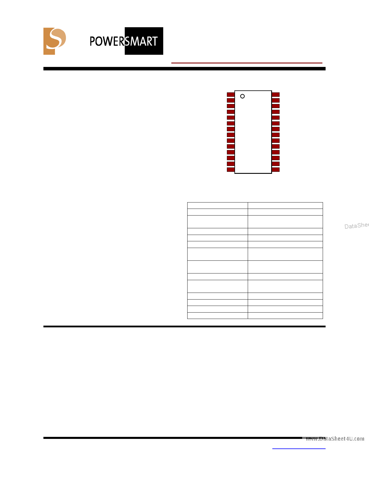
Pin Description
• Performs all major Li Ion, NiMH battery
monitoring and reporting functions
providing up to 1% accuracy in capacity
SWITCH
EE-SCK
1
2
28 VDSS
27 SMB-CLK
measurement
• Additional output pin for over voltage or
over temperature safety fuse operation
(SAFEOUT)
EE-Cf S
VREFT
VNTC
VCELL1
VASS1
3 26
4 PS331 25
5 24
6 23
7 22
SMB-DTA
LED 1
LED 2
LED 3
LED 4
• Fully compliant with industry standard
Smart Battery Data Specification V1.1a
- SMBus V1.1 with PEC/CRC-8
communication with system host
VCELL2
VCELL3
VCELL4
VADD
VSHP
8
9
10
11
12
21 SAFEOUT
20 VDDD
19 EE-SI
18 EE-SI/SO
17 OSCIN
• High accuracy measurement of charge /
discharge current, voltage, and
temperature with on-chip 14-bit integrating
A/D
VSHM
VASS2
13 16
14 15
0.209 mil SSOP
28-PIN Package
OSCOUT
VREG
• Precise capacity reporting for all lithium
and nickel chemistries using PowerSmart
Pin Summary
patented algorithms and 3D battery cell
Pin Name
models
INPUT
•
•
3D models and “learned” parameters
EE-SCK, EE-CS,
spStruooprgeprdoarmitnsmecaxebtlellercnovanilafEigSEuMPraBRtiuOosnMsin;otfeufrl1flay-4cfeieceldllDsreai-ntaSheet4EVVVUENRC.-cTEESoCFLIm/LTS1O-4
series
VASS1, VADD,
• Extremely low power operation:
VASS2
Function
LED Switch Input
SPI Serial EEPROM
Interface
Reference Voltage Output
Temperature A/D Input
Single Cell Voltage Inputs
Analog Supply Voltage
Inputs
- Sleep Mode: < 10 uA typical
VSHP, VSHM
Current Sense Resistor
- Run Mode: < 500 uA typical
Inputs
- Sample Mode: < 250 uA typical
• PS31XX Modules available for quick
prototyping or production
• Complete hardware and software
development tools available
VREG
OSCOUT, OSCIN
VDDD, VDSS
SAFEOUT
LED1-4
Voltage Reg. Control Output
Xtal Oscillator Inputs (32
KHz)
Digital Power Supply Inputs
Safety Control Output
LED Output Driver pins
SMB-CLK, SMB-DTA SMBus Interface Pins
Product Overview
The PS331 is an advanced Smart Battery Monitor
IC from PowerSmart, incorporating the latest
Smart Battery System (SBS) Specification
updates and revisions. Included is an advanced
SMBus communications engine that is compliant
with the SMBus V1.1 Packet Error Checking
(PEC) CRC-8 error correction protocols. The
PS331 implements updated firmware to process
all the revised Smart Battery Data (SBData) V1.1
data values. The PS331 integrates an advanced
RISC microprocessor, a precise 14-bit digital to
analog converter, and an external serial
EEPROM for storage of key operational
parameters. An output pin is provided that can be
set to activate on an over-voltage or over-
temperature condition. This ‘SAFEOUT’ pin can
be used to activate a fuse or other safety device
for added safety in battery pack designs.
The PS331 can be easily customized for
applications of Nickel or Lithium based battery
cell chemistries using the external EEPROM.
Upgrades to previously assembled battery packs
are simple via the standard SMBus serial
communications interface.
DataSheet4U.com
Updated 9/18/00
Copyright PowerSmart, Inc., 2000
DataSheet4 U .com
1 www.powersmart.com
DataSheet4U.com
DataShee
1 page 
www.DataSheet4U.com
PowerSmart PS331 Data Sheet
PRELIMINARY
et4U.com
P3 Family User’s Guide:
6. SAFEOUT Pin
Applications Notes:
The PowerSmart PS331 SMBus Smart Battery
P3 Ex. Connection Diagrams
IC offers an additional safety output for use in Li
P3 PC Board Layout Guide
Ion battery pack applications. As in any
P3 Temperature Alarm Operation
SMBus/SBS system, the first level of safety is
P3 Calibration Explanations
the SMBus communications between the Smart
Development Tool Documentation:
Battery, the System Host, and the Smart Battery
Lithium Ion Workbook Guide
Charger. Charging messages such as
SBTool User’s Guide
ChargingCurrent and ChargingVoltage are sent
P3 Eval System Data Sheet
between the Smart Battery and the Smart
P3 Cal System Data Sheet
Battery Charger. AlarmWarning messages are
P3 Info / Test Board Data Sheet
sent between the Smart Battery, the Host, and
SBToolBox Data Sheet
the Smart Charger if the battery detects any
incorrect or unsafe conditions.
5. LED Pins
If LED’s are connected to the LEDX pins to form
The PowerSmart PS331 IC has an additional
a fuel-gauge display, and the SWITCH pin is
output pin (SAFEOUT pin) that is activated
shorted to the VDDD pin (IC supply), then the
whenever any individual cell voltage is
LED’s will illuminate for a duration of
measured above the SAFETY_VOLT limit or
N_DISPLAY periods of TWS:
when the measured temperature is greater than
the SAFETY_TEMP limit. The pin is reset to an
N_DISPLAY x TWS (500 msec) =
inactive state when the measured temperature is
below the AL_HI_TEMP limit and all the
LED ‘on’ duration
individual cell voltages are below the
The fuel-gauge display is based on the SBData
SAFE_VOLT limit. To prevent false triggering, a
value of RelativeStateOfCharge but may be
re-check timer requires the activation limits to be
configured for AbsoluteStateOfCharge using bit
exceeded for a programmable duration before
3 in the MANUF_MODE register in the external
the SAFEOUT pin is activated.
EEPROM.
DataSheet4U.com
This SAFEOUT pin may be used to activate a
For PS331 products, LEDx pins are fixed for
safety fuse; signal or control another safety
fuel-gauge display configuration only. The LED
device to disable a charge control MOSFET; or
display is lit to indicate the state of charge of the
to indicate an error condition to a host system
battery as follows:
through an interrupt line. The SAFEOUT pin
may be configured to output either logic HI
OUTPUT Pin #: 4
321
SOC Value: 100% 75% 50% 25%
(3.3V) or LOW (0V.)
In all cases, the least significant output pin
assigned as an LED output will always flash if
the SOC value is below 10%.
NOTE: During EEPROM programming and
default power-up operation, the SAFEOUT pin is
normally LOW (0V) in the PS331.
The “Polarity” bit in LED_POLARITY is used to
select an active high or active low output.
Normal polarity for an LED SOC bar-graph
requires this bit be set to active low output.
LED_POLARITY is valid for all methods
described below (bar graphs, conditional
outputs). In case that an output is calculated to 0
and the polarity bit was set to 1, then the output
is inverted and will become HIGH.
DataShee
Updated 9/18/00
DataSheet4U.coCmopyright PowerSmart, Inc., 2000
DataSheet4 U .com
5 www.powersmart.com
DataSheet4U.com
5 Page | ||
| Páginas | Total 10 Páginas | |
| PDF Descargar | [ Datasheet PS331.PDF ] | |
Hoja de datos destacado
| Número de pieza | Descripción | Fabricantes |
| PS331 | Programmable SMBus/I2C Smart Battery ic With Packet Error Checking | Power Smart |
| PS3316 | SMD Power Inductors Shielded | Premo |
| PS334 | Programmable Smbus Smart Battery ic | Power Smart |
| Número de pieza | Descripción | Fabricantes |
| SLA6805M | High Voltage 3 phase Motor Driver IC. |
Sanken |
| SDC1742 | 12- and 14-Bit Hybrid Synchro / Resolver-to-Digital Converters. |
Analog Devices |
|
DataSheet.es es una pagina web que funciona como un repositorio de manuales o hoja de datos de muchos de los productos más populares, |
| DataSheet.es | 2020 | Privacy Policy | Contacto | Buscar |