|
|
|
PDF TA3020 Data sheet ( Hoja de datos )
| Número de pieza | TA3020 | |
| Descripción | Digital Audio Amplifier Driver using Digital Power Processing | |
| Fabricantes | Tripath | |
| Logotipo | ||
1. TA3020 Hay una vista previa y un enlace de descarga de TA3020 (archivo pdf) en la parte inferior de esta página. Total 27 Páginas | ||
|
No Preview Available !
Tripath Technology, Inc. - Technical Information
TA 3 0 2 0
STEREO 300W (4Ω) CLASS-T DIGITAL AUDIO AMPLIFIER DRIVER
USING DIGITAL POWER PROCESSING (DPPTM ) TECHNOLOGY
Technical Information
Revision 3.0 – September 2003
GENERAL DESCRIPTION
The TA3020 is a two-channel, 300W (4Ω) per channel Amplifier Driver IC that uses Tripath’s proprietary Digital
Power Processing (DPPTM) technology. Class-T amplifiers offer both the audio fidelity of Class-AB and the
power efficiency of Class-D amplifiers.
APPLICATIONS
Audio/Video Amplifiers & Receivers
Pro-audio Amplifiers
Automobile Power Amplifiers
Subwoofer Amplifiers
BENEFITS
Reduced system cost with smaller/less
expensive power supply and heat sink
Signal fidelity equal to high quality Class-
AB amplifiers
High dynamic range compatible with
digital media such as CD and DVD
FEATURES
Class-T architecture
Proprietary Digital Power Processing technology
“Audiophile” Sound Quality
0.02% THD+N @ 50W, 8Ω
0.03% IHF-IM @ 30W, 8Ω
High Efficiency
95% @ 150W @ 8Ω
90% @ 275W @ 4Ω
Supports wide range of output power levels
Up to 300W/channel (4Ω), single-ended outputs
Up to 1000W (4Ω), bridged outputs
Output over-current protection
Over- and under-voltage protection
Thermally Enhanced 48-pin DIP (dual-inline
package)
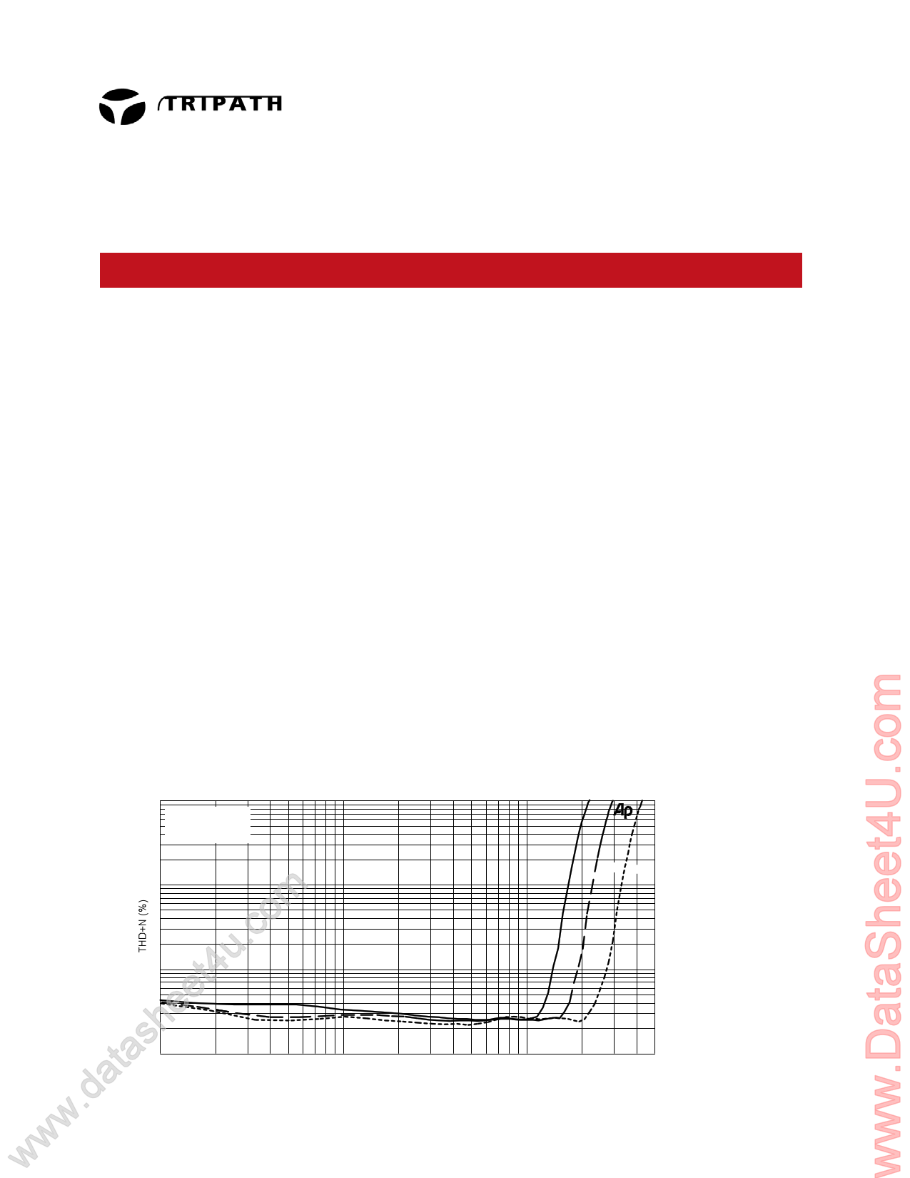
TYPICAL PERFORMANCE
10
f = 1kHz
5 BBM = 80nS
BW = 22Hz - 22kHz
THD+N versus Output Power versus Supply Voltage
RL = 4Ω
2
1
m0.5
.co0.2
u0.1
t40.05
ee0.02
sh0.01
ta 1
2
5
www.da1
10 20
Output Power (W)
50
100
39V 45V 54V
200 500
TA3020 – KL Rev. 3.0/09.03
1 page 
Tripath Technology, Inc. - Technical Information
Pin Description
Pin
1
2,48
3,47
4,46
5,45
6, 7
8, 9
10, 40
12, 31
13, 16
14, 18
15
17
19
20, 25
21, 26
22, 23
24
27, 35
28,34
29
30
32
33, 37
39
41, 42
43, 44
11, 36,
38
Function
VN10
LO2, LO1
LO2COM, LO1COM
HO2COM, HO1COM
HO2, HO1
OCS2LN, OCS2LP
OCS2HP, OCS2HN
VBOOT2, VBOOT1
OCR2
FBKOUT1, FBKOUT2
FBKGND1, FBKGND2
HMUTE
DCOMP
BIASCAP
INV2, INV1
OAOUT2, OAOUT1
BBM0, BBM1
MUTE
V5
AGND
VPPSENSE
VNNSENSE
REF
OCR1
VNN
OCS1LN, OCS1LP
OCS1HP, OCS1HN
NC
Description
“Floating” supply input for the FET drive circuitry. This voltage must be stable
and referenced to VNN.
Low side gate drive output (Channel 2 & 1)
Kelvin connection to source of low-side transistor (Channel 2 & 1)
Kelvin connection to source of high-side transistor (Channel 2 & 1)
High side gate drive output (Channel 2 & 1)
Over Current Sense inputs, Channel 2 low-side
Over Current Sense inputs, Channel 2 high-side
Bootstrapped voltage to supply drive to gate of high-side FET
(Channel 2 & 1)
Over-current threshold adjustment (Channel 2)
Switching feedback (Channels 1 & 2)
Ground Kelvin feedback (Channels 1 & 2)
Logic Output. A logic high indicates both amplifiers are muted, due to the
mute pin state, or a “fault” such as an overcurrent, undervoltage, or
overvoltage condition.
Internal mode selection. This pin must be grounded for proper device
operation.
Bandgap reference times two (typically 2.5VDC). Used to set the common
mode voltage for the input op amps. This pin is not capable of driving external
circuitry.
Inverting inputs of Input Stage op amps. (Channels 2 & 1)
Outputs of Input Stage op amps. (Channels 2 & 1)
Break-before-make timing control to prevent shoot-through in the output FETs.
Logic input. A logic high puts the amplifier in mute mode. Ground pin if not
used. Please refer to the section, Mute Control, in the Application Information.
5V power supply input.
Analog ground.
Positive supply voltage sense input. This pin is used for both over and
under voltage sensing for the VPP supply.
Negative supply voltage sense input. This pin is used for both over and under
voltage sensing for the VNN supply.
Used to set internal bias currents. The pin voltage is typically 1.1V.
Over-current threshold adjustment (Channel 1)
Negative supply voltage.
Over Current Sense inputs, Channel 1 low-side
Over Current Sense inputs, Channel 1 high-side
Not connected (bonded) internally. To minimize coupling between pins, tie
these pins to AGND (pin34).
5 TA3020 – KL Rev. 3.0/09.03
5 Page 
Typical Performance
Tripath Technology, Inc. - Technical Information
10
5 Pout = 40W/Channel
Vs =+28V
BW = 22Hz - 22kHz
2
1
0.5
THD+N versus Frequency versus Break Before Make
RL = 4Ω
0.2
BBM = 120nS
0.1
0.05
0.02
0.01
20
50 100 200
500 1k
Frequency (Hz)
BBM = 80nS
2k 5k
10k 20k
10
Pout = 40W/Channel
Vs =+28V
5 BBM = 80nS
THD+N versus Frequency versus Bandwidth
RL = 4Ω
2
1
0.5
0.2
0.1
BW = 30kHz
0.05
0.02
0.01
20
BW = 22kHz
50 100 200
500 1k
Frequency (Hz)
2k
5k 10k 20k
10
f = 1kHz
5 BBM = 80nS
BW = 22Hz - 22kHz
2
1
THD+N versus Output Power versus Supply Voltage
RL = 4Ω
23V 28V 35V
0.5
0.2
0.1
0.05
0.02
0.01
1
2
5 10 20
Output Power (W)
50 100 200
10
Pout = 20W/Channel
5 Vs =+28V
BW = 22Hz - 22kHz
THD+N versus Frequency versus Break Before Make
RL = 8Ω
2
1
0.5
0.2
BBM = 120nS
0.1
0.05
0.02
0.01
20
50 100 200
500 1k
Frequency (Hz)
BBM = 80nS
2k 5k
10k 20k
10
Pout = 20W/Channel
5 Vs =+28V
BBM = 80nS
2
1
0.5
THD+N versus Frequency versus Bandwidth
RL = 8Ω
0.2
0.1
0.05
0.02
0.01
20
BW = 30kHz
BW = 22kHz
50 100 200
500 1k
Frequency (Hz)
2k
5k 10k 20k
10
f = 1kHz
5 BBM = 80nS
BW = 22Hz - 22kHz
2
1
0.5
THD+N versus Output Power versus Supply Voltage
RL = 8Ω
23V 28V 35V
0.2
0.1
0.05
0.02
0.01
2
5 10 20
50 100 200
Output Power (W)
11 TA3020 – KL Rev. 3.0/09.03
11 Page | ||
| Páginas | Total 27 Páginas | |
| PDF Descargar | [ Datasheet TA3020.PDF ] | |
Hoja de datos destacado
| Número de pieza | Descripción | Fabricantes |
| TA3020 | Digital Audio Amplifier Driver using Digital Power Processing | Tripath |
| Número de pieza | Descripción | Fabricantes |
| SLA6805M | High Voltage 3 phase Motor Driver IC. |
Sanken |
| SDC1742 | 12- and 14-Bit Hybrid Synchro / Resolver-to-Digital Converters. |
Analog Devices |
|
DataSheet.es es una pagina web que funciona como un repositorio de manuales o hoja de datos de muchos de los productos más populares, |
| DataSheet.es | 2020 | Privacy Policy | Contacto | Buscar |