|
|
|
PDF MPX50 Data sheet ( Hoja de datos )
| Número de pieza | MPX50 | |
| Descripción | Uncompensated Silicon Pressure Sensors | |
| Fabricantes | Motorola Semiconductors | |
| Logotipo | ||
1. MPX50 Datasheet sensor Hay una vista previa y un enlace de descarga de MPX50 (archivo pdf) en la parte inferior de esta página. Total 10 Páginas | ||
|
No Preview Available !
MOTOROLA
SEMICONDUCTOR TECHNICAL DATA
Order this document
by MPX50/D
50 kPa
Uncompensated
Silicon Pressure Sensors
The MPX50 silicon piezoresistive pressure sensor provides a very accurate and linear
voltage output — directly proportional to the applied pressure. This standard, low cost,
uncompensated sensor permits manufacturers to design and add their own external
temperature compensating and signal conditioning networks. Compensation techniques
are simplified because of the predictability of Motorola’s single element strain gauge
design.
Features
• Low Cost
• Patented Silicon Shear Stress Strain Gauge Design
• Ratiometric to Supply Voltage
• Easy to Use Chip Carrier Package Options
• 60 mV Span (Typ)
• Differential and Gauge Options
• ± 0.25% (Max) Linearity
Application Examples
• Air Movement Control
• Environmental Control Systems
• Level Indicators
• Leak Detection
• Medical Instrumentation
• Industrial Controls
• Pneumatic Control Systems
• Robotics
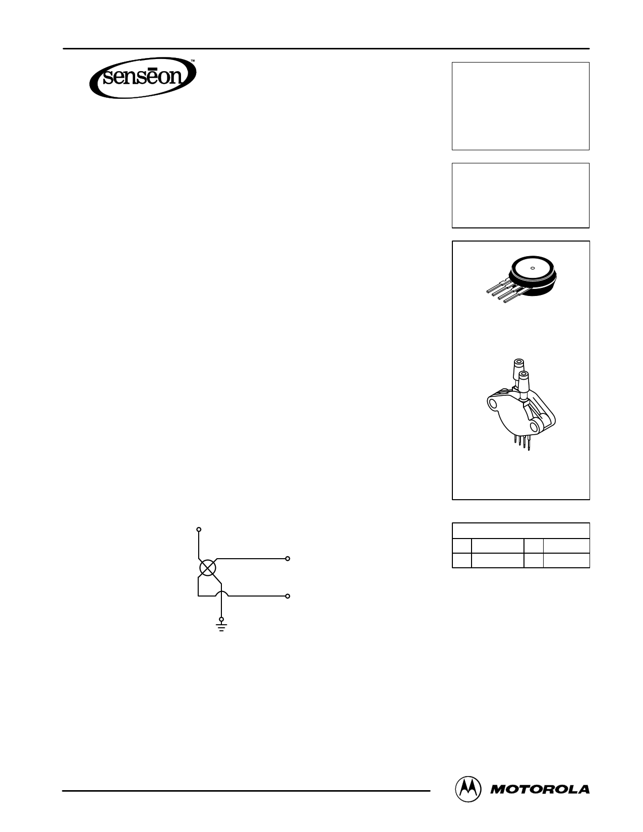
Figure 1 shows a schematic of the internal circuitry on the stand–alone pressure
sensor chip.
PIN 3 + VS
X–ducer
PIN 2
+ Vout
PIN 4
– Vout
PIN 1
Figure 1. Uncompensated Pressure Sensor Schematic
VOLTAGE OUTPUT versus APPLIED DIFFERENTIAL PRESSURE
The differential voltage output of the X–ducer is directly proportional to the differential
pressure applied.
The output voltage of the differential or gauge sensor increases with increasing
pressure applied to the pressure side (P1) relative to the vacuum side (P2). Similarly,
output voltage increases as increasing vacuum is applied to the vacuum side (P2)
relative to the pressure side (P1).
Senseon and X–ducer are trademarks of Motorola, Inc.
REV 5
©MMoottoororolal,aInSc.e1n9s97or Device Data
MPX50
SERIES
0 to 50 kPa (0 – 7.25 psi)
60 mV FULL SCALE SPAN
(TYPICAL)
BASIC CHIP
CARRIER ELEMENT
CASE 344–15, STYLE 1
DIFFERENTIAL
PORT OPTION
CASE 344C–01, STYLE 1
NOTE: Pin 1 is the notched pin.
PIN NUMBER
1 Gnd 3 VS
2 +Vout 4 –Vout
1
1 page 
PACKAGE DIMENSIONS
MPX50 SERIES
C
POSITIVE
R PRESSURE (P1)
M
B –A–
PIN 1
1234
N
L
–T–
SEATING
PLANE
J POSITIVE
PRESSURE
F
(P1) D 4 PL
G
0.136 (0.005) M T A M
CASE 344–15
ISSUE W
NOTES:
1. DIMENSIONING AND TOLERANCING PER ASME
Y14.5M, 1994.
2. CONTROLLING DIMENSION: INCH.
3. DIMENSION –A– IS INCLUSIVE OF THE MOLD
STOP RING. MOLD STOP RING NOT TO EXCEED
16.00 (0.630).
INCHES
DIM MIN MAX
A 0.595 0.630
B 0.514 0.534
C 0.200 0.220
D 0.016 0.020
F 0.048 0.064
G 0.100 BSC
J 0.014 0.016
L 0.695 0.725
M 30_ NOM
N 0.475 0.495
R 0.430 0.450
MILLIMETERS
MIN MAX
15.11 16.00
13.06 13.56
5.08 5.59
0.41 0.51
1.22 1.63
2.54 BSC
0.36 0.40
17.65 18.42
30_ NOM
12.07 12.57
10.92 11.43
STYLE 1:
PIN 1. GROUND
2. + OUTPUT
3. + SUPPLY
4. – OUTPUT
PORT #2
VACUUM
PRESSURE
(P2)
–B– V
C
N
R
SEATING
PLANE
–T–
POSITIVE
PRESSURE
(P1)
PIN 1
A
12 34
K
S
JG
F
D 4 PL
0.13 (0.005) M T B M
CASE 344A–01
ISSUE B
NOTES:
1. DIMENSIONING AND TOLERANCING PER ANSI
Y14.5M, 1982.
2. CONTROLLING DIMENSION: INCH.
INCHES
DIM MIN MAX
A 0.690 0.720
B 0.245 0.255
C 0.780 0.820
D 0.016 0.020
F 0.048 0.064
G 0.100 BSC
J 0.014 0.016
K 0.345 0.375
N 0.300 0.310
R 0.178 0.186
S 0.220 0.240
V 0.182 0.194
MILLIMETERS
MIN MAX
17.53 18.28
6.22 6.48
19.81 20.82
0.41 0.51
1.22 1.63
2.54 BSC
0.36 0.41
8.76 9.53
7.62 7.87
4.52 4.72
5.59 6.10
4.62 4.93
STYLE 1:
PIN 1. GROUND
2. + OUTPUT
3. + SUPPLY
4. – OUTPUT
Motorola Sensor Device Data
5
5 Page | ||
| Páginas | Total 10 Páginas | |
| PDF Descargar | [ Datasheet MPX50.PDF ] | |
Hoja de datos destacado
| Número de pieza | Descripción | Fabricantes |
| MPX50 | Uncompensated Silicon Pressure Sensors | Motorola Semiconductors |
| MPX5010 | INTEGRATED PRESSURE SENSOR | Motorola Semiconductors |
| MPX5010 | Integrated Silicon Pressure Sensor | Freescale Semiconductor |
| MPX5050 | OPERATING OVERVIEW INTEGRATED PRESSURE SENSOR | Motorola Semiconductors |
| Número de pieza | Descripción | Fabricantes |
| SLA6805M | High Voltage 3 phase Motor Driver IC. |
Sanken |
| SDC1742 | 12- and 14-Bit Hybrid Synchro / Resolver-to-Digital Converters. |
Analog Devices |
|
DataSheet.es es una pagina web que funciona como un repositorio de manuales o hoja de datos de muchos de los productos más populares, |
| DataSheet.es | 2020 | Privacy Policy | Contacto | Buscar |