|
|
|
PDF MAX6964 Data sheet ( Hoja de datos )
| Número de pieza | MAX6964 | |
| Descripción | 17-Output LED Driver/GPO | |
| Fabricantes | Maxim Integrated | |
| Logotipo | ||
Hay una vista previa y un enlace de descarga de MAX6964 (archivo pdf) en la parte inferior de esta página. Total 23 Páginas | ||
|
No Preview Available !
19-3179; Rev 3; 3/05
EVAALVUAAILTAIOBNLEKIT
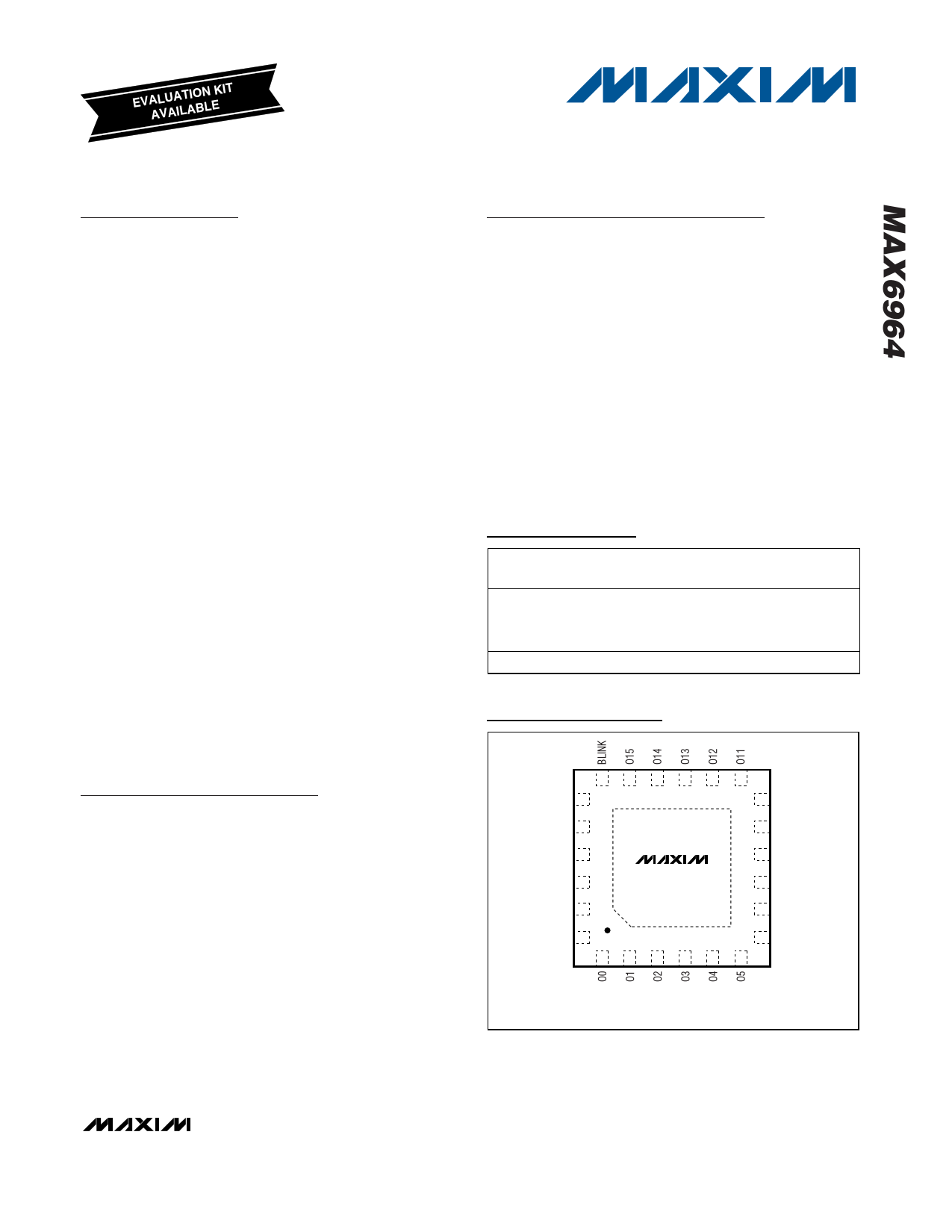
17-Output LED Driver/GPO with
Intensity Control and Hot-Insertion Protection
General Description
The MAX6964 I2C-compatible serial interfaced periph-
eral provides microprocessors with 17 output ports.
Each output is an open-drain current-sinking output
rated at 50mA and 7V. The outputs are capable of dri-
ving LEDs, or providing logic outputs with external
resistive pullup up to 7V.
Eight-bit PWM current control is also integrated. Four of
the bits are global control and apply to all LED outputs
to provide coarse adjustment of current from fully off to
fully on with 14 intensity steps. Additionally, each output
has an individual 4-bit control, which further divides the
globally set current into 16 more steps. Alternatively,
the current control can be configured as a single 8-bit
control that sets all outputs at once.
Each output has independent blink timing with two blink
phases. LEDs can be individually set to be either on or
off during either blink phase, or to ignore the blink con-
trol. The blink period is controlled by an external clock
(up to 1kHz) on BLINK or by a register. The BLINK
input can also be used as a logic control to turn the
LEDs on and off, or as a general-purpose input (GPI).
The MAX6964 supports hot insertion. The SDA, SCL,
RST, BLINK, and the slave address input ADO remain
high impedance in power-down (V+ = 0V) with up to 6V
asserted upon them. The output ports remain high
impedance with up to 8V asserted upon them.
The MAX6964 is controlled through a 2-wire I2C
serial interface, and can be configured to one of four
I2C addresses.
Applications
LCD Backlights
LED Status Indication
Keypad Backlights
RGB LED Drivers
Typical Application Circuit at end of data sheet.
Features
♦ 400kbps, 2-Wire Serial Interface, 5.5V Tolerant
♦ 2V to 3.6V Operation
♦ Overall 8-Bit PWM LED Intensity Control
Global 16-Step Intensity Control
Plus Individual 16-Step Intensity Controls
♦ Two-Phase LED Blinking
♦ High Port Output Current—Each Port 50mA (max)
♦ RST Input Clears the Serial Interface and
Restores Power-Up Default State
♦ Supports Hot Insertion
♦ Outputs are 7V-Rated Open Drain
♦ Low Standby Current (1.2µA (typ), 3.3µA (max))
♦ Small 4mm x 4mm, 0.8mm High Thin QFN Package
♦ -40°C to +125°C Temperature Range
Ordering Information
PART
TEMP RANGE
PIN-
PACKAGE
PKG CODE
24 Thin QFN
MAX6964ATG -40°C to +125°C 4mm x 4mm
x 0.8mm
MAX6964AEG -40°C to +125°C 24 QSOP
T2444-4
—
Pin Configurations
TOP VIEW
18 17 16 15 14 13
SCL 19
12 O10
SDA 20
11 O9
V+ 21
O16 22
MAX6964
10 O8
9 GND
RST 23
8 O7
AD0 24
7 O6
12345 6
QFN
Pin Configurations continued at end of data sheet.
________________________________________________________________ Maxim Integrated Products 1
For pricing, delivery, and ordering information, please contact Maxim/Dallas Direct! at
1-888-629-4642, or visit Maxim’s website at www.maxim-ic.com.
1 page 
17-Output LED Driver/GPO with
Intensity Control and Hot-Insertion Protection
(TA = +25°C, unless otherwise noted.)
SCOPE SHOT OF OUTPUT PORTS
MAX6964 toc07
MASTER INTENSITY SET TO 14/15
OUTPUT 1,
2V/div
OUTPUT 1 INDIVIDUAL INTENSITY
SET TO 1/16
OUTPUT 2 INDIVIDUAL INTENSITY
SET TO 14/15
2ms/div
OUTPUT 2,
2V/div
Typical Operating Characteristics (continued)
SCOPE SHOT OF OUTPUT PORTS
MAX6964 toc08
MASTER INTENSITY SET TO 1/15
OUTPUT 1
2V/div
OUTPUT 1 INDIVIDUAL INTENSITY
SET TO 1/16
OUTPUT 2 INDIVIDUAL INTENSITY
SET TO 15/16
2ms/div
OUTPUT 2
2V/div
SINK CURRENT vs. VOL
0.35
ONLY ONE OUTPUT LOADED
0.30 V+ = 2V
0.25
0.20
V+ = 2.7V
V+ = 3.3V
0.15
V+ = 3.6V
0.10
0.05
0
0 10 20 30 40 50
SINK CURRENT (mA)
Pin Description
PIN
QSOP
QFN
1, 4–11, 13–20 1–8, 10–17, 22
2 23
3 24
12 9
21 18
22 19
23 20
24 21
— Pad
NAME
FUNCTION
O0-O16 Output Ports. Open-drain outputs rated at 7V, 50mA.
RST Reset Input. Active low clears the 2-wire interface and puts the device in the
same condition as power-up reset.
AD0
Address Input. Sets device slave address. Connect to either GND, V+, SCL, or
SDA to give 4 logic combinations. See Table 1.
GND
Ground. Do not sink more than 350mA into the GND pin.
BLINK
Input Port. Configurable as blink control or general-purpose input.
SCL I2C-Compatible Serial Clock Input
SDA
I2C-Compatible Serial Data I/O
V+ Positive Supply Voltage. Bypass V+ to GND with a 0.047µF ceramic capacitor.
Exposed Pad Exposed pad on package underside. Connect to GND.
_______________________________________________________________________________________ 5
5 Page 
17-Output LED Driver/GPO with
Intensity Control and Hot-Insertion Protection
Table 3. Power-Up Configuration
REGISTER FUNCTION
Blink phase 0 outputs O7–O0
Blink phase 0 outputs O15–O8
User RAM0
User RAM1
Blink phase 1 outputs O7–O0
Blink phase 1 outputs O15–O8
Master and global/O16
intensity
POWER-UP CONDITION
High-impedance outputs
High-impedance outputs
0xFF
0xFF
High-impedance outputs
High-impedance outputs
PWM oscillator is disabled;
O16 is static logic output
ADDRESS
CODE
REGISTER DATA
(hex)
D7 D6 D5 D4 D3 D2 D1 D0
0x02
11111111
0x03
11111111
0x06
11111111
0x07
11111111
0x0A
11111111
0x0B
11111111
0x0E
00001111
Configuration
Outputs intensity O1, O0
Outputs intensity O3, O2
Outputs intensity O5, O4
Outputs intensity O7, O6
Outputs intensity O9, O8
Outputs intensity O11, O10
Outputs intensity O13, O12
Outputs intensity O15, O14
O16 is high-impedance output;
blink is disabled;
global intensity is enabled
O1, O0 are static logic outputs
O3, O2 are static logic outputs
O5, O4 are static logic outputs
O7, O6 are static logic outputs
O9, O8 are static logic outputs
O11, O10 are static logic outputs
O13, O12 are static logic outputs
O15, O14 are static logic outputs
0x0F
0x10
0x11
0x12
0x13
0x14
0x15
0x16
0x17
00110100
11111111
11111111
11111111
11111111
11111111
11111111
11111111
11111111
Table 4. Configuration Register
REGISTER
ADDRESS
CODE
REGISTER DATA
(hex)
D7 D6 D5 D4 D3 D2 D1 D0
R/W
CONFIGURATION
Write device configuration
Read back device configuration
Disable blink
Enable blink
Flip blink register (see text)
X = Don’t care.
0 0x0F
1
—
—
—
—
XX
BLINK O1 O0
GBE
00
XXXXXXX0
XXXXXXX1
XXXXXX01
XXXXXX11
______________________________________________________________________________________ 11
11 Page | ||
| Páginas | Total 23 Páginas | |
| PDF Descargar | [ Datasheet MAX6964.PDF ] | |
Hoja de datos destacado
| Número de pieza | Descripción | Fabricantes |
| MAX696 | Microprocessor Supervisory Circuits | Maxim Integrated |
| MAX6960 | 4-Wire Serially Interfaced 8 x 8 Matrix Graphic LED Drivers | Maxim Integrated Products |
| MAX6961 | 4-Wire Serially Interfaced 8 x 8 Matrix Graphic LED Drivers | Maxim Integrated Products |
| MAX6962 | 4-Wire Serially Interfaced 8 x 8 Matrix Graphic LED Drivers | Maxim Integrated Products |
| Número de pieza | Descripción | Fabricantes |
| SLA6805M | High Voltage 3 phase Motor Driver IC. |
Sanken |
| SDC1742 | 12- and 14-Bit Hybrid Synchro / Resolver-to-Digital Converters. |
Analog Devices |
|
DataSheet.es es una pagina web que funciona como un repositorio de manuales o hoja de datos de muchos de los productos más populares, |
| DataSheet.es | 2020 | Privacy Policy | Contacto | Buscar |