|
|
|
PDF MAX920 Data sheet ( Hoja de datos )
| Número de pieza | MAX920 | |
| Descripción | SOT23 / 1.8V / Nanopower / Beyond-the-Rails Comparators With/Without Reference | |
| Fabricantes | Maxim Integrated | |
| Logotipo | ||
1. MAX920 Hay una vista previa y un enlace de descarga de MAX920 (archivo pdf) en la parte inferior de esta página. Total 12 Páginas | ||
|
No Preview Available !
19-1512; Rev 0; 7/99
SOT23, 1.8V, Nanopower, Beyond-the-Rails
Comparators With/Without Reference
General Description
The MAX917–MAX920 nanopower comparators in
space-saving SOT23 packages feature Beyond-the-
Rails™ inputs and are guaranteed to operate down to
+1.8V. The MAX917/MAX918 feature an on-board
1.245V ±1.5% reference and draw an ultra-low supply
current of only 750nA, while the MAX919/MAX920 (with-
out reference) require just 380nA of supply current.
These features make the MAX917–MAX920 family of
comparators ideal for all 2-cell battery applications,
including monitoring/management.
The unique design of the output stage limits supply-cur-
rent surges while switching, virtually eliminating the
supply glitches typical of many other comparators. This
design also minimizes overall power consumption
under dynamic conditions. The MAX917/MAX919 have
a push/pull output stage that sinks and sources current.
Large internal output drivers allow Rail-to-Rail® output
swing with loads up to 8mA. The MAX918/MAX920
have an open-drain output stage that makes them suit-
able for mixed-voltage system design.
Applications
2-Cell Battery Monitoring/Management
Ultra-Low-Power Systems
Mobile Communications
Notebooks and PDAs
Threshold Detectors/Discriminators
Sensing at Ground or Supply Line
Telemetry and Remote Systems
Medical Instruments
Selector Guide
PART
MAX917
MAX918
MAX919
MAX920
INTERNAL
REFERENCE
Yes
Yes
No
No
OUTPUT
TYPE
Push/Pull
Open-Drain
Push/Pull
Open-Drain
SUPPLY
CURRENT
(nA)
750
750
380
380
Typical Application Circuit appears at end of data sheet.
Features
o Ultra-Low Supply Current
380nA per Comparator (MAX919/MAX920)
750nA per Comparator with Reference
(MAX917/MAX918)
o Guaranteed to Operate Down to +1.8V
o Internal 1.245V ±1.5% Reference
(MAX917/MAX918)
o Input Voltage Range Extends 200mV
Beyond-the-Rails
o CMOS Push/Pull Output with ±8mA Drive
Capability (MAX917/MAX919)
o Open-Drain Output Versions Available
(MAX918/MAX920)
o Crowbar-Current-Free Switching
o Internal Hysteresis for Clean Switching
o No Phase Reversal for Overdriven Inputs
o Space-Saving SOT23 Package
Ordering Information
PART
MAX917EUK-T
MAX917ESA
MAX918EUK-T
MAX918ESA
MAX919EUK-T
MAX919ESA
MAX920EUK-T
MAX920ESA
TEMP.
RANGE
PIN-
SOT
PACKAGE TOP MARK
-40°C to +85°C 5 SOT23-5
-40°C to +85°C 8 SO
ADIQ
—
-40°C to +85°C 5 SOT23-5 ADIR
-40°C to +85°C 8 SO
—
-40°C to +85°C 5 SOT23-5
-40°C to +85°C 8 SO
ADIS
—
-40°C to +85°C 5 SOT23-5 ADIT
-40°C to +85°C 8 SO
—
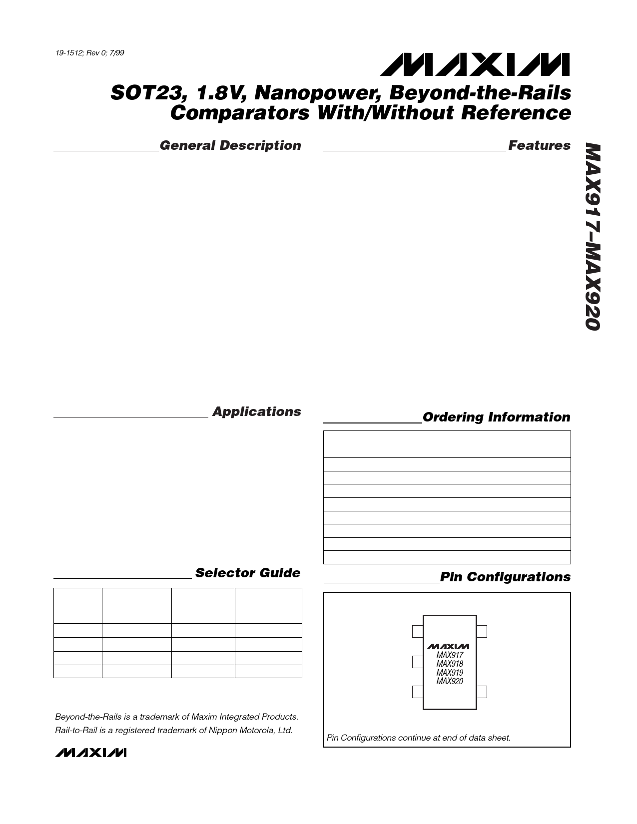
Pin Configurations
TOP VIEW
OUT 1
VEE 2
IN+ 3
MAX917
MAX918
MAX919
MAX920
5 VCC
4 IN- (REF)
Beyond-the-Rails is a trademark of Maxim Integrated Products.
Rail-to-Rail is a registered trademark of Nippon Motorola, Ltd.
( ) ARE FOR MAX917/MAX918.
SOT23-5
Pin Configurations continue at end of data sheet.
________________________________________________________________ Maxim Integrated Products 1
For free samples & the latest literature: http://www.maxim-ic.com, or phone 1-800-998-8800.
For small orders, phone 1-800-835-8769.
1 page 
SOT23, 1.8V, Nanopower, Beyond-the-Rails
Comparators With/Without Reference
Typical Operating Characteristics
(VCC = +5V, VEE = 0, CL = 15pF, VOVERDRIVE = 100mV, TA = +25°C, unless otherwise noted.)
MAX917/MAX918
SUPPLY CURRENT vs.
SUPPLY VOLTAGE AND TEMPERATURE
900
TA = +85°C
MAX919/MAX920
SUPPLY CURRENT vs.
SUPPLY VOLTAGE AND TEMPERATURE
600
MAX917/MAX918
SUPPLY CURRENT vs. TEMPERATURE
900
850
800
TA = +25°C
700
600 TA = -40°C
TA = +85°C
500
TA = +25°C
400
TA = -40°C
800 VCC = 5V
750
700 VCC = 3V
650 VCC = 1.8V
600
550
500
1.5 2.0 2.5 3.0 3.5 4.0 4.5 5.0 5.5
SUPPLY VOLTAGE (V)
300
1.5 2.0 2.5 3.0 3.5 4.0 4.5 5.0 5.5
SUPPLY VOLTAGE (V)
500
-40
-15 10 35 60
TEMPERATURE (°C)
85
MAX919/MAX920
SUPPLY CURRENT vs. TEMPERATURE
550
500
VCC = 5V
450
VCC = 3V
400
350
VCC = 1.8V
300
-40
-15 10 35 60
TEMPERATURE (°C)
85
MAX917/MAX918
SUPPLY CURRENT vs.
OUTPUT TRANSITION FREQUENCY
16
14 VCC = 5V
12
10
8 VCC = 3V
6
4
2
VCC = 1.8V
0
1 10 100 1k 10k 100k
OUTPUT TRANSITION FREQUENCY (Hz)
MAX919/MAX920
SUPPLY CURRENT vs.
OUTPUT TRANSITION FREQUENCY
14
12 VCC = 5V
10
8
6 VCC = 3V
4
2
0 VCC = 1.8V
1 10 100 1k 10k 100k
OUTPUT TRANSITION FREQUENCY (Hz)
OUTPUT VOLTAGE LOW vs. SINK CURRENT
450
400 VCC = 1.8V VCC = 3V
350
300 VCC = 5V
250
200
150
100
50
0
0 2 4 6 8 10 12 14 16
SINK CURRENT (mA)
OUTPUT VOLTAGE LOW vs. SINK CURRENT
AND TEMPERATURE
600
500
400 TA = +25°C
300 TA = +85°C
200
TA = -40°C
100
0
0 2 4 6 8 10 12 14 16
SINK CURRENT (mA)
MAX917/MAX919
OUTPUT VOLTAGE HIGH vs. SOURCE CURRENT
0.6
VCC = 1.8V
0.5
VCC = 3V
VCC = 5V
0.4
0.3
0.2
0.1
0
0 2 4 6 8 10 12 14 16 18 20
SOURCE CURRENT (mA)
_______________________________________________________________________________________ 5
5 Page 
SOT23, 1.8V, Nanopower, Beyond-the-Rails
Comparators With/Without Reference
IN+
VTHR
IN-
VTHF
VHB
THRESHOLDS
HYSTERESIS
BAND
OUT
VCC
R3
R1
VIN
R2
VREF
VCC
OUT
VEE
MAX917
MAX919
Figure 2. Threshold Hysteresis Band
Additional Hysteresis (MAX917/MAX919)
The MAX917/MAX919 have a 4mV internal hysteresis
band (VHB). Additional hysteresis can be generated
with three resistors using positive feedback (Figure 3).
Unfortunately, this method also slows hysteresis re-
sponse time. Use the following procedure to calculate
resistor values.
1) Select R3. Leakage current at IN is under 2nA, so
the current through R3 should be at least 0.2µA to
minimize errors caused by leakage current. The cur-
rent through R3 at the trip point is (VREF - VOUT)/R3.
Considering the two possible output states in solving
for R3 yields two formulas: R3 = VREF/IR3 or R3 =
(VCC - VREF)/IR3. Use the smaller of the two resulting
resistor values. For example, when using the
MAX917 (VREF = 1.245V) and VCC = 5V, and if we
choose IR3 = 1µA, then the two resistor values are
1.2MΩ and 3.8MΩ. Choose a 1.2MΩ standard value
for R3.
2) Choose the hysteresis band required (VHB). For this
example, choose 50mV.
3) Calculate R1 according to the following equation:
R1 = R3 (VHB / VCC)
For this example, insert the values
R1 = 1.2MΩ (50mV/5V) = 12kΩ
4) Choose the trip point for VIN rising (VTHR) such that
VTHR > VREF · (R1 + R3)/R3 (VTHF is the trip point for
VIN falling). This is the threshold voltage at which the
comparator switches its output from low to high as
VIN rises above the trip point. For this example,
choose 3V.
5) Calculate R2 as follows:
R2 = 1/[VTHR/(VREF · R1) - (1 / R1) - (1 / R3)]
Figure 3. MAX917/MAX919 Additional Hysteresis
R2 = 1/[3.0V/(1.2V · 12kΩ) - (1 / 12kΩ) -
(1/1.2MΩ)] = 8.05kΩ
For this example, choose an 8.2kΩ standard value.
6) Verify the trip voltages and hysteresis as follows:
VIN rising: VTHR = VREF · R1 [(1 / R1) + (1 / R2)
+ (1 / R3)]
VIN falling: VTHF = VTHR - (R1 · VCC / R3)
Hysteresis = VTHR - VTHF
Additional Hysteresis (MAX918/MAX920)
The MAX918/MAX920 have a 4mV internal hysteresis
band. They have open-drain outputs and require an
external pull-up resistor (Figure 4). Additional hystere-
sis can be generated using positive feedback, but the
formulas differ slightly from those of the MAX917/
MAX919. Use the following procedure to calculate
resistor values.
1) Select R3 according to the formulas R3 = VREF / 1µA
or R3 = (VCC - VREF)/1µA - R4. Use the smaller of
the two resulting resistor values.
2) Choose the hysteresis band required (VHB).
3) Calculate R1 according to the following equation:
R1 = (R3 + R4) (VHB/VCC)
4) Choose the trip point for VIN rising (VTHR) (VTHF is
the trip point for VIN falling). This is the threshold
voltage at which the comparator switches its output
from low to high as VIN rises above the trip point.
5) Calculate R2 as follows:
( )⋅
R2 = 1/VTHR/ VREF
R1
−
1
R1
−
1
R3
______________________________________________________________________________________ 11
11 Page | ||
| Páginas | Total 12 Páginas | |
| PDF Descargar | [ Datasheet MAX920.PDF ] | |
Hoja de datos destacado
| Número de pieza | Descripción | Fabricantes |
| MAX920 | SOT23 / 1.8V / Nanopower / Beyond-the-Rails Comparators With/Without Reference | Maxim Integrated |
| MAX9201 | (MAX9201 - MAX9203) Low-Power Voltage Comparators | Maxim Integrated Products |
| MAX9202 | (MAX9201 - MAX9203) Low-Power Voltage Comparators | Maxim Integrated Products |
| MAX9203 | (MAX9201 - MAX9203) Low-Power Voltage Comparators | Maxim Integrated Products |
| Número de pieza | Descripción | Fabricantes |
| SLA6805M | High Voltage 3 phase Motor Driver IC. |
Sanken |
| SDC1742 | 12- and 14-Bit Hybrid Synchro / Resolver-to-Digital Converters. |
Analog Devices |
|
DataSheet.es es una pagina web que funciona como un repositorio de manuales o hoja de datos de muchos de los productos más populares, |
| DataSheet.es | 2020 | Privacy Policy | Contacto | Buscar |