|
|
|
PDF MAX814 Data sheet ( Hoja de datos )
| Número de pieza | MAX814 | |
| Descripción | 1% Accuracy / Low-Power / +3V and +5V P Supervisory Circuits | |
| Fabricantes | Maxim Integrated | |
| Logotipo | ||
Hay una vista previa y un enlace de descarga de MAX814 (archivo pdf) en la parte inferior de esta página. Total 16 Páginas | ||
|
No Preview Available !
19-0412; Rev 0; 6/95
±1% Accuracy, Low-Power, +3V and +5V
µP Supervisory Circuits
_______________General Description ____________________________Features
The MAX814/MAX815/MAX816 are high-accuracy
microprocessor (µP) supervisory circuits that provide
power-on reset, watchdog, and power-fail functions.
They eliminate manual trimming and improve reliability
in critical applications needing high-accuracy reset
thresholds. The RESET output is guaranteed to be in
the correct state for VCC down to 1V. The reset com-
parator is designed to ignore fast transients on VCC.
Reset thresholds are available for operation with a vari-
ety of 3V and 5V supply voltages.
A 75µA maximum supply current makes the MAX814/
MAX815/MAX816 ideal for use in portable equipment.
All three devices are available in 8-pin DIP and SO
packages. See the Selector Table below for a review of
features.
_____________________Selector Table
FEATURE
RESET Output
RESET Output
Manual Reset
MAX814 MAX815 MAX816
o ±1% Worst-Case Reset Threshold Accuracy
o 4.8V, 4.7V, 4.55V, 3.03V, or Adjustable Reset
Thresholds
o ±1% Low-Line Threshold Accuracy (MAX814)
60mV Above Reset Threshold
o 200ms Reset Time Delay
o Active-Low RESET Output
Active-High RESET Output (MAX814/MAX816)
o 75µA Max Supply Current
o Guaranteed RESET Valid to VCC = 1V
o Manual Reset Input
o ±2% Power-Fail Comparator
o Independent Watchdog with 1.56sec Timeout
(MAX815)
o Power-Supply Glitch Immunity
o 8-Pin SO and DIP Packages
VCC Reset Voltage
Power-Fail Monitor
Low-Line Detector
Watchdog Circuit
K, L, N, T K, L, N, T Adjustable
_____________Reset Trip Thresholds
SUFFIX
MAX814/MAX815
RESET TRIP THRESHOLD
MIN (V)
MAX (V)
________________________Applications
Medical Equipment
Controllers
Intelligent Instruments
Critical µP Power Monitoring
Portable/Battery-Powered Equipment
Set-Top Boxes
K
4.75
4.85
L
4.65
4.75
N
4.50
4.60
T
3.00
3.06
MAX816
— Adjustable
Ordering Information appears at end of data sheet.
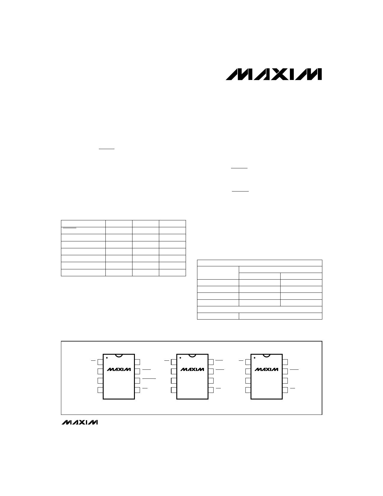
__________________________________________________________Pin Configurations
TOP VIEW
MR 1
VCC 2
GND 3
PFI 4
MAX814
8 RESET
7 RESET
6 LOW LINE
5 PFO
MR 1
VCC 2
GND 3
PFI 4
MAX815
8 WDO
7 RESET
6 WDI
5 PFO
DIP/SO
DIP/SO
MR 1
VCC 2
GND 3
PFI 4
MAX816
8 RESET
7 RESET
6 RESET IN
5 PFO
DIP/SO
________________________________________________________________ Maxim Integrated Products 1
Call toll free 1-800-998-8800 for free samples or literature.
1 page 
±1% Accuracy, Low-Power, +3V and +5V
µP Supervisory Circuits
__________________________________________Typical Operating Characteristics
(TA = +25°C, unless otherwise noted.)
VCC SUPPLY CURRENT vs. TEMPERATURE
3V PARTS (MAX814T/MAX815T, MAX816)
70
65 VCC = 5.0V
60
55
VCC = 3.3V
50
45 VCC = 2.5V
40
35
30
-60 -40 -20 0 20 40 60
TEMPERATURE (°C)
80 100
RESET-COMPARATOR PROPAGATION
DELAY vs. TEMPERATURE
40
100mV OVERDRIVE
35 (VRT - VCC)
30
25
20
15
-60 -40 -20 0 20 40 60 80 100
TEMPERATURE (°C)
LOW-LINE TO RESET THRESHOLD vs.
TEMPERATURE (VCC RISING)
70
68
66
64
62
60
58
56
54
52
50
-60 -40 -20 0 20 40 60
TEMPERATURE (°C)
80 100
VCC SUPPLY CURRENT vs. TEMPERATURE
5V PARTS (MAX814/MAX815K, L, N)
70
65
60
VCC = 5.0V
55
50
45 VCC = 3.3V
40
35
30
-60 -40 -20 0 20 40 60
TEMPERATURE (°C)
80 100
PFI THRESHOLD vs. TEMPERATURE
3V PARTS (MAX814T/MAX815T, MAX816)
1.715
1.710
1.705
1.700
1.695
1.690
1.685
1.680
1.675
1.670
-60 -40 -20 0 20 40 60
TEMPERATURE (°C)
80 100
LOW-LINE TO RESET THRESHOLD vs.
TEMPERATURE (VCC FALLING)
70
68
66
64
62
60
58
56
54
52
50
-60 -40 -20 0 20 40 60 80 100
TEMPERATURE (°C)
RESET TIMEOUT PERIOD
vs. TEMPERATURE
200
195
190 VCC = 3.3V
185
180 VCC = 5.0V
175
-60 -40 -20 0 20 40 60
TEMPERATURE (°C)
80 100
PFI THRESHOLD vs. TEMPERATURE
5V PARTS (MAX814/MAX815K, L, N)
2.550
2.540
2.530
2.520
2.510
2.500
2.490
2.480
2.470
2.460
2.450
-60 -40 -20 0 20 40 60 80 100
TEMPERATURE (°C)
LOW-LINE COMPARATOR
PROPAGATION DELAY vs. TEMPERATURE
60
100mV OVERDRIVE
50 (VLLT - VCC)
40
30
20
10
0
-60 -40 -20 0 20 40 60
TEMPERATURE (°C)
80 100
_______________________________________________________________________________________ 5
5 Page 
±1% Accuracy, Low-Power, +3V and +5V
µP Supervisory Circuits
(VRT) is greater than or equal to the minimum IC operat-
ing voltages (VICMIN). The 1% “L” series allows the use
of a 5V ±5% power supply, and guarantees system
operation over worst-case conditions, maximizing the
Power-Supply Guard-Band Range.
T-suffix parts have a minimum reset threshold set to
3.00V, worst case. They are intended for 3.3V systems
(3.33V ±0.26V) with a 7.8% or better power-supply tol-
erance. Typically, the reset threshold (VRT) is greater
than or equal to the minimum IC operating voltages
(VICMIN).
The MAX816 has an adjustable reset threshold, set with
an external resistive divider (Figure 3). The voltage on
the RESET IN pin is monitored, not the voltage on VCC.
The RESET IN threshold is 1.700V, and has very high
impedance and 35nA maximum leakage. Calculate the
trip point, VRT, as follows:
( )VRT
=
VRIT
× R1+ R2
R2
where VRT = the desired reset threshold, VRIT is the
RESET IN threshold (1.700V), R1 is the resistor con-
nected between VRT and RESET IN, and R2 is the
resistor connected between RESET IN and GND.
Resistors R1 and R2 can have very high values. The
usual procedure is to set R2 to some conveniently high
value (100kΩ, for example) and calculate R1 based on
the desired reset threshold, using the following formula:
[ ]( )R1 = R2 × VRT / VRIT −1
The MAX816 can achieve ±1.2% accuracy with 0.1%
resistors.
Watchdog Timer (MAX815)
The watchdog circuit monitors the µP’s activity. If the µP
does not toggle the watchdog input (WDI) within the
watchdog timeout period (tWP), WDO goes low (Figure
8). WDO also goes low during reset conditions.
Whenever VCC is below the reset threshold, WDO stays
low; however, unlike RESET, WDO does not have a mini-
mum pulse width. As soon as VCC rises above the reset
threshold, WDO goes high with no delay (Figure 9).
Typically, WDO is connected to the non-maskable inter-
rupt (NMI) of a µP. When VCC drops below the reset
threshold, WDO goes low whether or not the watchdog
timer has timed out (Figure 9). This would normally trig-
ger an NMI interrupt, but RESET goes low simultane-
ously and thus overrides the NMI interrupt.
Connecting WDO to MR enables the watchdog timeout
to generate a reset in the MAX815.
Early Power-Fail Warning
Critical systems often require early warning to indicate
when power is failing. This warning provides time for
the µP to store vital data and take care of any additional
“housekeeping” before the power supply gets too far
out of tolerance for the µP to operate reliably.
Power-Fail Comparator
The power-fail comparator is intended as an undervolt-
age detector to signal a failing power supply. However,
the comparator does not need to be dedicated to this
function, because it is completely separate from the
rest of the circuitry. To build an early-warning circuit for
power failure, connect the PFI pin to a voltage divider
(see Figures 1, 2, and 3). Choose the voltage divider
ratio, so the voltage at PFI falls below VPFI just before
the monitored voltage drops out. Use PFO to interrupt
the µP, so it can prepare for an orderly power-down.
The power-fail input (PFI) is compared to an internal
reference. If the voltage on PFI is less than the power-
fail reference, PFO sinks at least 1.2mA to GND; other-
wise it sources at least 300µA from VCC. The reference
is 2.50V in the MAX814/MAX815 with K, L, N suffixes, or
1.70V with the T suffix. It is also 1.70V in the MAX816.
LOW LINE Output (MAX814)
The low-line detector is a separate comparator that
monitors VCC with a typical threshold voltage of 60mV
above the normal reset threshold, with 2mV of hystere-
sis (Figure 9). If VCC rises faster than 10µs/V, insert a
100pF capacitor from LOW LINE to GND to ensure
proper start-up. For normal operation (VCC above the
reset threshold), LOW LINE is pulled to VCC. Use LOW
LINE to provide an NMI to the µP when power begins to
fall. In most battery-operated portable systems, reserve
energy in the battery provides ample time to complete
the shutdown routine once the low-line warning is
encountered, and before reset asserts. If the system
must also contend with a more rapid VCC fall time—
such as when the main battery is disconnected or a
high-side switch is opened during operation—use
capacitance on the VCC line to provide time to execute
the shutdown routine. First, calculate the worst-case
time required for the system to perform its shutdown
routine. Then use the worst-case shutdown time
(tSHDN), worst-case load current (ILOAD), and minimum
low-line to reset threshold (VLR) to calculate the amount
of capacitance required to allow the shutdown routine
to complete before reset is asserted.
CHOLD
=
ILOAD × tSHDN
VLR
______________________________________________________________________________________ 11
11 Page | ||
| Páginas | Total 16 Páginas | |
| PDF Descargar | [ Datasheet MAX814.PDF ] | |
Hoja de datos destacado
| Número de pieza | Descripción | Fabricantes |
| MAX810 | 3-Pin Microprocessor Reset Monitors | ON |
| MAX810 | (MAX809 / MAX810) 3-pin microprocessor resets | NXP Semiconductors |
| MAX810L | 3-Pin Microprocessor Reset Circuits | Maxim Integrated |
| MAX810M | 3-Pin Microprocessor Reset Circuits | Maxim Integrated |
| Número de pieza | Descripción | Fabricantes |
| SLA6805M | High Voltage 3 phase Motor Driver IC. |
Sanken |
| SDC1742 | 12- and 14-Bit Hybrid Synchro / Resolver-to-Digital Converters. |
Analog Devices |
|
DataSheet.es es una pagina web que funciona como un repositorio de manuales o hoja de datos de muchos de los productos más populares, |
| DataSheet.es | 2020 | Privacy Policy | Contacto | Buscar |