|
|
|
PDF MAX776 Data sheet ( Hoja de datos )
| Número de pieza | MAX776 | |
| Descripción | -5V/-12V/-15V or Adjustable / High-Efficiency / Low IQ Inverting DC-DC Controllers | |
| Fabricantes | Maxim Integrated | |
| Logotipo | ||
Hay una vista previa y un enlace de descarga de MAX776 (archivo pdf) en la parte inferior de esta página. Total 16 Páginas | ||
|
No Preview Available !
19-0191; Rev 2; 12/02
EVAALVUAAILTAIOBNLEKIT
-5V/-12V/-15V or Adjustable, High-Efficiency,
Low IQ Inverting DC-to-DC Controllers
General Description
The MAX774/MAX775/MAX776 inverting switching
regulators deliver high efficiency over three decades of
load current. A unique current-limited, pulse-
frequency modulated (PFM) control scheme provides
the benefits of pulse-width modulation (high efficiency
with heavy loads), while using less than 100µA of supply
current (vs. 2mA to 10mA for PWM converters). The result
is high efficiency over a wide range of loads.
These ICs also use tiny external components; their high
switching frequency (up to 300kHz) allows for less than
5mm diameter surface-mount magnetics.
The MAX774/MAX775/MAX776 accept input voltages from
3V to 16.5V, and have preset output voltages of
-5V, -12V, and -15V, respectively. Or, the output voltage
can be user-adjusted with two resistors. Maximum
VIN - VOUT differential voltage is limited only by the break-
down voltage of the chosen external switch transistor.
These inverters use external P-channel MOSFET switches,
allowing them to power loads up to 5W. If less power is
required, use the MAX764/MAX765/MAX766 inverting
switching regulators with on-board MOSFETs.
Applications
LCD-Bias Generators
High-Efficiency DC-to-DC Converters
Battery-Powered Applications
Data Communicators
Features
o 85% Efficiency for 5mA to 1A Load Currents
o Up to 5W Output Power
o 100µA (max) Supply Current
o 5µA (max) Shutdown Current
o 3V to 16.5V Input Range
o -5V (MAX774), -12V (MAX775), -15V (MAX776),
or Adjustable Output Voltage
o Current-Limited PFM Control Scheme
o 300kHz Switching Frequency
Ordering Information
PART
MAX774CPA
MAX774CSA
MAX774C/D
MAX774EPA
MAX774ESA
MAX774MJA
TEMP RANGE
0°C to +70°C
0°C to +70°C
0°C to +70°C
-40°C to +85°C
-40°C to +85°C
-55°C to +125°C
*Contact factory for dice specifications.
PIN-PACKAGE
8 Plastic DIP
8 SO
Dice*
8 Plastic DIP
8 SO
8 CERDIP
Ordering Information continued on last page.
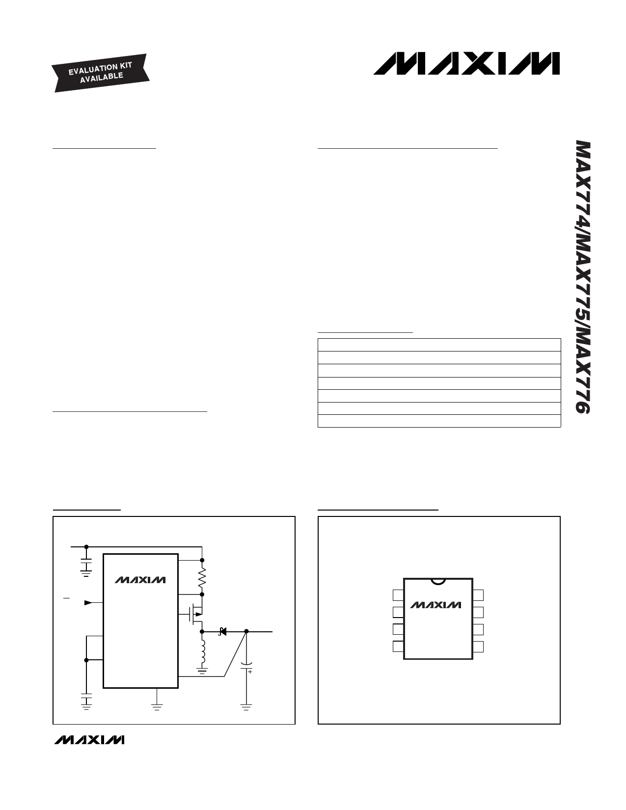
Typical Operating Circuit
INPUT
3V TO 16V
V+
ON/OFF
MAX774
SHDN
CS
EXT
FB
REF
OUT
GND
P
OUTPUT
-5V
TOP VIEW
Pin Configuration
OUT 1
FB 2
SHDN 3
REF 4
MAX774
MAX775
MAX776
DIP/SO
8 GND
7 EXT
6 CS
5 V+
________________________________________________________________ Maxim Integrated Products 1
For pricing, delivery, and ordering information, please contact Maxim/Dallas Direct! at
1-888-629-4642, or visit Maxim’s website at www.maxim-ic.com.
1 page 
-5V/-12V/-15V or Adjustable, High-Efficiency,
Low IQ Inverting DC-to-DC Controllers
_____________________________Typical Operating Characteristics (continued)
(TA = +25°C, unless otherwise noted.)
STARTUP VOLTAGE
vs. LOAD CURRENT (BOOTSTRAPPED)
5.0
VOUT = -15V
4.5
VOUT = -12V
4.0
3.5
VOUT = -5V
3.0
2.5
1
10 100 1000
LOAD CURRENT (mA)
EXT RISE AND FALL TIMES
vs. TEMPERATURE
130
CEXT = 1nF
120
110
100
5V RISE
90
80
5V FALL
70
60
12V RISE
50
40
30 12V FALL
20
-60 -40 -20 0 20 40 60 80 100 120 140
TEMPERATURE (°C)
STARTUP VOLTAGE
vs. LOAD CURRENT (NONBOOTSTRAPPED)
5.0
VOUT = -12V
4.5
VOUT = -15V
4.0
VOUT = -24V
3.5
3.0 VOUT = -5V
2.5
0.1
1 10 100
LOAD CURRENT (mA)
1000
EXT RISE AND FALL TIMES
vs. TEMPERATURE
500
CEXT = 5nF
450
400
5V RISE
350
300
250
5V FALL
200
12V RISE
150
100 12V FALL
50
-60 -40 -20 0 20 40 60 80 100 120 140
TEMPERATURE (°C)
MAX774
MAXIMUM LOAD vs. INPUT VOLTAGE
2200
VOUT = -5V
2000
1800
BOOTSTRAPPED
1600
1400
1200
NONBOOTSTRAPPED
1000
800
2
4 6 8 10 12 14 16
INPUT VOLTAGE (V)
SWITCH ON-TIME vs. TEMPERATURE
17
V+ = 5V
16
15
-60
0 60
TEMPERATURE (°C)
120
SWITCH OFF-TIME vs. TEMPERATURE
2.5
V+ = 5V
2.0
1.5
-60
0 60
TEMPERATURE (°C)
120
SWITCH ON-TIME/OFF-TIME RATIO
8.0
V+ = 5V
7.8
7.6
7.4
7.2
7.0
6.8
6.6
6.4
6.2
6.0
-60 -40 -20 0 20 40 60 80 100 120 140
TEMPERATURE (°C)
SHUTDOWN CURRENT
vs. TEMPERATURE
4.0
3.5
3.0
2.5
V+ = 15V
2.0
1.5
1.0 V+ = 8V
0.5
V+ = 4V
0
-60 -40 -20 0 20 40 60 80 100 120 140
TEMPERATURE (°C)
_______________________________________________________________________________________ 5
5 Page 
-5V/-12V/-15V or Adjustable, High-Efficiency,
Low IQ Inverting DC-to-DC Controllers
0.1µF
VOUT
RZ
R2
R1
0.1µF
1
OUT
8
GND
2
FB
MAX774
MAX775
MAX776
4 REF
6V ≤ VZ + VIN ≤ 10V
VOUT – VZ
RZ
> IZ
IZ = ZENER BREAKDOWN CURRENT
VZ = ZENER BREAKDOWN VOLTAGE
VIN = INPUT SUPPLY VOLTAGE
Figure 5. Connection Using Zener Diode to Boost Base Drive
connected to the output voltage (-5V, -12V, -15V). In
nonbootstrapped operation, OUT is connected to
ground, and EXT now swings from V+ to ground.
At high input-to-output differentials, it may be neces-
sary to use nonbootstrapped mode to avoid the 21V V+
to VOUT maximum rating. Also, observe the VGS maxi-
mum rating of the external transistor. At intermediate
voltages and currents, the advantages of bootstrapped
vs. nonbootstrapped operation are slight. When input
voltages are less than about 4V, always use the boot-
strapped circuit.
Shutdown and Quiescent Current
The MAX774/MAX775/MAX776 are designed to save
power in battery-powered applications. A TTL/CMOS
logic-level shutdown input (SHDN) has been provided
for the lowest-power applications. When shut down
(SHDN = V+), most internal bias current sources and
the reference are turned off so that less than 5µA of
current is drawn.
In normal operation, the quiescent current will be less
than 100µA. However, this current is measured by forc-
ing the external switch transistor off. Even with no load,
in an actual application, additional current will be
drawn to supply the feedback resistors’ and the diode’s
and capacitor’s leakage current. Under no-load condi-
tions, you should see a short current pulse at half the
peak current approximately every 100ms (the exact
period depends on actual circuit leakages).
EXT Drive Voltages
EXT swings from OUT to V+ and provides the drive out-
put for an external power MOSFET. When using the on-
chip feedback resistors for the preset output voltages,
the voltage at OUT equals the output voltage. When
using external feedback resistors, OUT may be tied to
GND or some other potential between VOUT and GND.
Always observe the V+ to OUT absolute maximum rat-
ing of 21V. For V+ to output differentials greater than
21V, OUT must be tied to a potential more positive than
the output and, therefore, the output voltage must be
set with an external resistor divider.
In nonbootstrapped operation with low input voltages
(<4V), tie OUT to a negative voltage to fully enhance the
external MOSFET. Accomplish this by creating an inter-
mediate voltage for VOUT with a zener diode (Figure 5).
__________________Design Procedure
Setting the Output Voltage
The MAX774/MAX775/MAX776 are preset for -5V, -12V,
and -15V output voltages, respectively; however, they
may also be adjusted to other values with an external
voltage divider. For the preset output voltage, connect
FB to REF and connect OUT to the output (Figure 3). In
this case, the output voltage is sensed by OUT.
For an adjustable output (Figures 3 and 4), connect an
external resistor divider from the output voltage to FB,
and from FB to REF. In this case, the divided-down out-
put voltage is sensed via the FB pin.
There are three reasons to use the external resistor divider:
1) An output voltage other than a preset value is
desired.
2) The input-to-output differential exceeds 21V.
3) The output voltage (VOUT to GND) exceeds -15V.
See Figures 3 and 4 for adjustable operation. The
impedance of the feedback network should be low
enough that the input bias current of FB is not a factor.
For best efficiency and precision, allow 10µA to flow
through the network. Calculate (VREF - VFB) / R1 =
10µA. Since VREF = 1.5V and VFB = 0V, R1 becomes
150kΩ. Then calculate R2 as follows:
_R_2_ = _V__O_U__T_
R1 VREF
(or, _V_O__U_T_= 10µA)
R2
Choosing an Inductor
Practical inductor values range from 10µH to 50µH.
The maximum inductor value is not particularly critical.
For highest current at high VOUT to V+ ratios, the
______________________________________________________________________________________ 11
11 Page | ||
| Páginas | Total 16 Páginas | |
| PDF Descargar | [ Datasheet MAX776.PDF ] | |
Hoja de datos destacado
| Número de pieza | Descripción | Fabricantes |
| MAX770 | 5V/12V/15V or Adjustable / High-Efficiency / Low IQ / Step-Up DC-DC Controllers | Maxim Integrated |
| MAX7705 | P Power-Supply Monitor with Reset | Maxim Integrated |
| MAX771 | 5V/12V/15V or Adjustable / High-Efficiency / Low IQ / Step-Up DC-DC Controllers | Maxim Integrated |
| MAX772 | 5V/12V/15V or Adjustable / High-Efficiency / Low IQ / Step-Up DC-DC Controllers | Maxim Integrated |
| Número de pieza | Descripción | Fabricantes |
| SLA6805M | High Voltage 3 phase Motor Driver IC. |
Sanken |
| SDC1742 | 12- and 14-Bit Hybrid Synchro / Resolver-to-Digital Converters. |
Analog Devices |
|
DataSheet.es es una pagina web que funciona como un repositorio de manuales o hoja de datos de muchos de los productos más populares, |
| DataSheet.es | 2020 | Privacy Policy | Contacto | Buscar |