|
|
|
PDF RF9678 Data sheet ( Hoja de datos )
| Número de pieza | RF9678 | |
| Descripción | W-CDMA TRANSMIT MODULATOR AND IF AGC | |
| Fabricantes | RF Micro Devices | |
| Logotipo | ||
Hay una vista previa y un enlace de descarga de RF9678 (archivo pdf) en la parte inferior de esta página. Total 16 Páginas | ||
|
No Preview Available !
Preliminary
RF9678
5 W-CDMA TRANSMIT MODULATOR AND IF AGC
Typical Applications
• W-CDMA Systems
• EDGE Systems
• CDMA Systems
• TDMA Systems
Product Description
The RF9678 is an integrated complete quadrature modu-
lator and IF AGC amplifier designed for the transmit sec-
tion of W-CDMA applications. It is designed to modulate
baseband I and Q signals, and amplify the resulting IF
signals while providing 55dB of gain control range. This
circuit is designed as part of RFMD’s single mode
W-CDMA Chipset, which also includes the RF2679
W-CDMA Receive IF AGC and Demodulator. The IC is
manufactured on an advanced Silicon Bi-CMOS process,
and is supplied in a16-pin leadless chip carrier.
Optimum Technology Matching® Applied
Si BJT
üSi Bi-CMOS
GaAs HBT
SiGe HBT
GaAs MESFET
Si CMOS
16 15 14 13
VGC 1
Gain Control
12 NC
VCC2 2
MOD+ 3
MOD- 4
5
S
Quad
/2
67
11 BG OUT
10 LO+
9 LO-
8
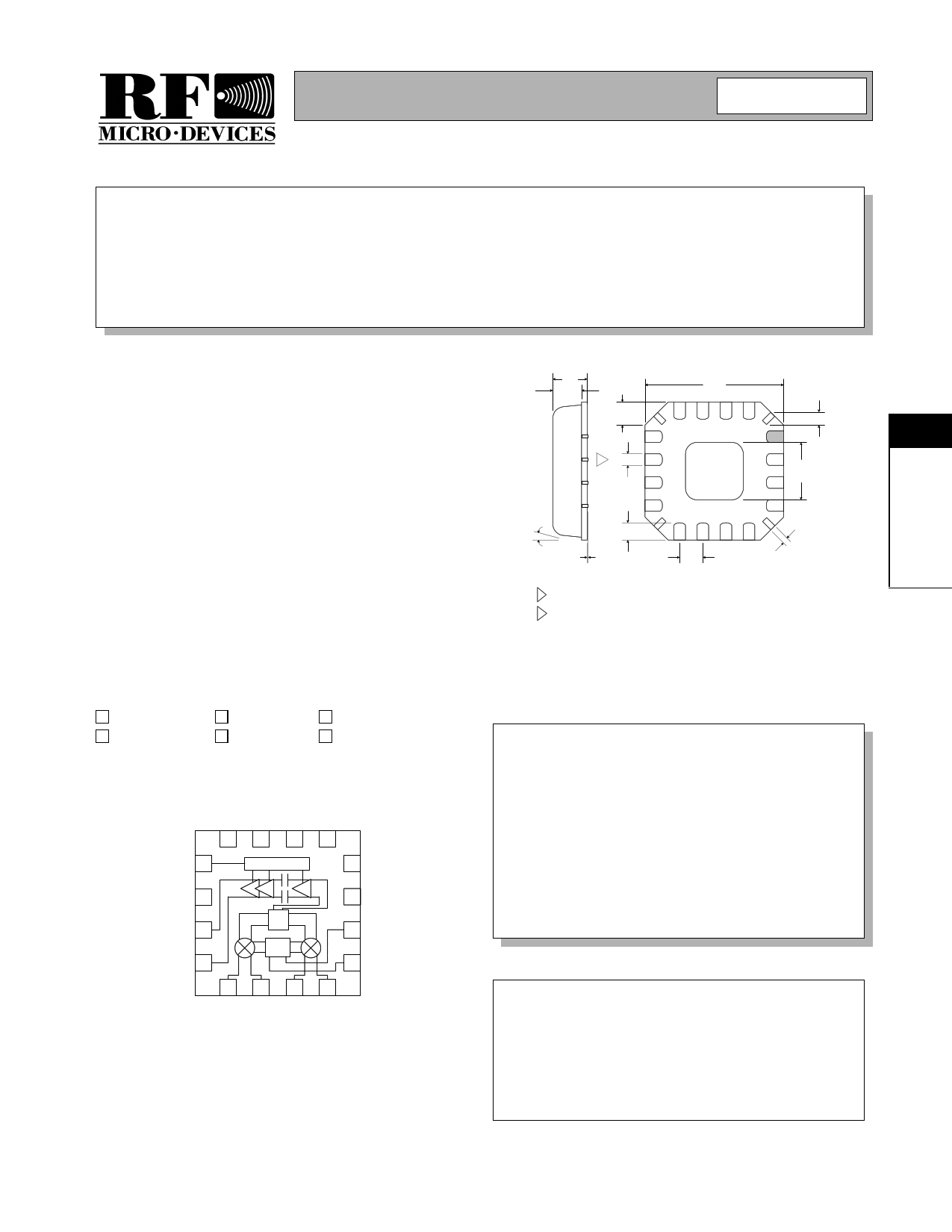
1.00
.80 0.85
.65
.60
.24 typ
.35
2 .23
4.00
sq.
.65
.30
4 PLCS
1.85
1.55 sq.
12°
max
.05
.01
NOTES:
.75
.50
.23
.13
.65 4 PLCS
Dimensions in mm.
1 Shaded Pin is Lead 1.
2
Dimension applies to plated terminal and is measured between 0.02 mm and
0.25 mm from terminal end.
3 Pin 1 identifier must exist on top surface of package by identification mark or
feature on the package body. Exact shape and size is optional.
4 Package Warpage: 0.05 max.
5 Die thickness allowable: 0.305 mm max.
Package Style: LCC, 16-Pin, 4x4
Features
• Digitally Controlled Power Down Modes
• 2.7V to 3.3V Operation
• Digital LO Quadrature Divider
• AGC Linearity/Current Consumption Var.
• IF AGC Amp with 55dB Gain Control
Ordering Information
RF9678
W-CDMA Transmit Modulator and IF AGC
RF9678 PCBA Fully Assembled Evaluation Board
Functional Block Diagram
RF Micro Devices, Inc.
7628 Thorndike Road
Greensboro, NC 27409, USA
Tel (336) 664 1233
Fax (336) 664 0454
http://www.rfmd.com
5
Rev A4 010622
5-91
1 page 
Preliminary
RF9678
Application Notes
Quadrature modulator performance can be correlated to a set of specifications known as Carrier and Sideband Suppres-
sion. In addition, Sideband Suppression can be correlated with the amplitude and phase balance of the In-Phase (I) and
Quadrature (Q) signals and Carrier Suppression can be correlated to the DC offset between the I and Q signals (see Fig-
ure 1). For a more thorough discussion of the theory and mathematics behind these specifications refer to RF Micro
Devices application note AN0001.
In-Phase Signal
Quadrature Signal
LO Signal
0°
90°
Σ RF Output Signal
5
Figure 1. Quadrature Modulator Block Diagram
Effects of Carrier Suppression and Sideband Suppression on W-CDMA (QPSK) Modulation
W-CDMA signals may be displayed on a vector signal analyzer as a collection of points called a constellation. Each point
in the constellation is called a symbol and is representative of a bit sequence. In QPSK modulation, there are four sym-
bols and each symbol is representative of two data bits (see Figure 2). The I and Q signals are added together to create
a vector of precise phase and amplitude. The vector is then sampled at a rate called the symbol rate and it's position at
these intervals corresponds to the target symbol locations. Errors in the phase and amplitude of the I and Q signals will
translate to errors in the vector's phase and amplitude. This phase and amplitude error will result in a displacement of the
vector from it's target symbol point. A measurement of this error is called the Error Vector Magnitude (EVM) and it repre-
sents the magnitude of the displacement of the actual vector from it's target location.
Ref Lvl
0 dBm
1.5
IMAG
CF 380 MHz Meas Signal
SR 3.84 MHz Constellation
Demod
QPSK
A
T1
EXT
-1.5
-1.875
Date:
6.FEB.2001 01:20:38
Figure 2. W-CDMA (QPSK) Constellation
REAL
1.875
QPSK constellation points exist on a circle of constant radius around the origin. Amplitude errors result in symbol points
being displaced either inside or outside of their target locations on this circle. Phase errors result in symbol points being
displaced on an arc either to the left or right of their target location. Finally, DC offset errors cause the origin to shift,
resulting in a constant I and Q offset of all target points (see Figure 3).
Rev A4 010622
5-95
5 Page 
Preliminary
Pin Out
RF9678
16 15 14 13
VGC 1
12 NC
VCC2 2
11 BG OUT
MOD+ 3
10 LO+
MOD- 4
9 LO-
5678
Application Schematic
VPD
VGC
VCC
VCC
2200 pF
MOD+
VCC
15 nH
MOD-
15 nH
2200 pF
1 nF
1500
Ω
10 nF
VCC
39 kΩ
16 15 14 13
10 nF
10 nF
10 pF
1
2
3
4
Gain Control
Σ
Quad
/2
12
10 nF
11
1 nF
10
1 nF
9
LO IN
5678
10 pF
Q SIG-
Q SIG+
I SIG-
I SIG+
5
Rev A4 010622
5-101
11 Page | ||
| Páginas | Total 16 Páginas | |
| PDF Descargar | [ Datasheet RF9678.PDF ] | |
Hoja de datos destacado
| Número de pieza | Descripción | Fabricantes |
| RF9678 | W-CDMA TRANSMIT MODULATOR AND IF AGC | RF Micro Devices |
| RF9678PCBA | W-CDMA TRANSMIT MODULATOR AND IF AGC | RF Micro Devices |
| Número de pieza | Descripción | Fabricantes |
| SLA6805M | High Voltage 3 phase Motor Driver IC. |
Sanken |
| SDC1742 | 12- and 14-Bit Hybrid Synchro / Resolver-to-Digital Converters. |
Analog Devices |
|
DataSheet.es es una pagina web que funciona como un repositorio de manuales o hoja de datos de muchos de los productos más populares, |
| DataSheet.es | 2020 | Privacy Policy | Contacto | Buscar |