|
|
|
PDF EMB35N04V Data sheet ( Hoja de datos )
| Número de pieza | EMB35N04V | |
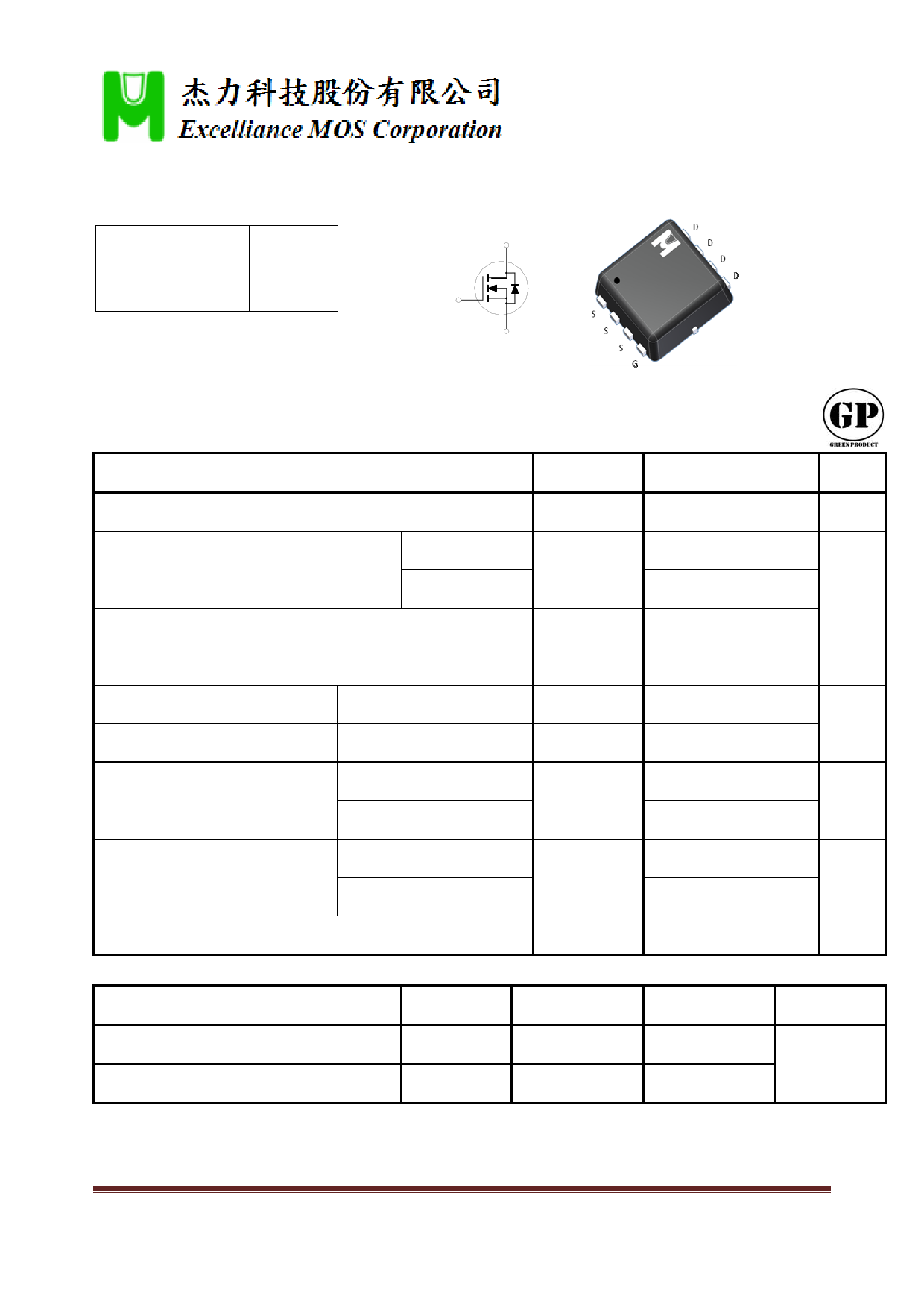
| Descripción | Field Effect Transistor | |
| Fabricantes | Excelliance MOS | |
| Logotipo | ||
Hay una vista previa y un enlace de descarga de EMB35N04V (archivo pdf) en la parte inferior de esta página. Total 5 Páginas | ||
|
No Preview Available !
N‐Channel Logic Level Enhancement Mode Field Effect Transistor
Product Summary:
BVDSS
40V
D
RDSON (MAX.)
28mΩ
ID 12A G
UIS, Rg 100% Tested
S
Pb‐Free Lead Plating & Halogen Free
ABSOLUTE MAXIMUM RATINGS (TC = 25 °C Unless Otherwise Noted)
PARAMETERS/TEST CONDITIONS
SYMBOL
Gate‐Source Voltage
Continuous Drain Current
Pulsed Drain Current1
TC = 25 °C
TC = 100 °C
Avalanche Current
Avalanche Energy
Repetitive Avalanche Energy2
L = 0.1mH, ID=8A, RG=25Ω
L = 0.05mH
Power Dissipation
TC = 25 °C
TC = 100 °C
Power Dissipation
TA = 25 °C
TA = 100 °C
Operating Junction & Storage Temperature Range
VGS
ID
IDM
IAS
EAS
EAR
PD
PD
Tj, Tstg
THERMAL RESISTANCE RATINGS
THERMAL RESISTANCE
SYMBOL
TYPICAL
Junction‐to‐Case
RJC
Junction‐to‐Ambient3
RJA
1Pulse width limited by maximum junction temperature.
2Duty cycle 1%
350°C / W when mounted on a 1 in2 pad of 2 oz copper.
2013/9/3
EMB35N04V
LIMITS
±20
12
9
48
8
3.2
1.6
21
8.3
2.5
1
‐55 to 150
UNIT
V
A
mJ
W
W
°C
MAXIMUM
6
50
UNIT
°C / W
p.1
1 page 
EMB35N04V
10
I D = 8A
Gate Charge Characteristics
8
6
VD S = 15V 20V
4
Capacitance Characteristics
800
f = 1MHz
VG S = 0 V
600
Ciss
400
2
0
0
4 8 12
Q g ‐ Gate Charge(nC)
16
200
0
0
Coss
Crss
10 20 30
VD S ‐ Drain‐Source Voltage( V )
40
100
Maximum Safe Operating Area
10 R D S ( O N ) Limit
100μs
1ms
10ms
100ms
1
0.1
VG S = 10V
Single Pulse
R J A = 50°C/W
TA = 25°C
1s
10s
DC
0.01
0.1
1 10
VD S ‐ Drain‐Source Voltage( V )
100
Single Pulse Maximum Power Dissipation
50
Single Pulse
Rθ J A = 50°C/W
40 TA = 25°C
30
20
10
0
0.001
0.01 0.1
1
10 100 1000
1
Duty Cycle = 0.5
Transient Thermal Response Curve
0.2
0.1
0.1
0.05
0.02
0.01
0.01
Single Pulse
0.001
10 ‐4
10 ‐3
10 ‐2
10 ‐1
1
t 1 ,Time (sec)
Notes:
P DM
t1
1.Duty Cycle,D = t2 t1
t2
2.R θ J A = 50°C/W
3.TJ ‐ TA = P * Rθ J A (t)
4.Rθ J A (t)=r(t) + RθJA
10 100
1000
2013/9/3
p.5
5 Page | ||
| Páginas | Total 5 Páginas | |
| PDF Descargar | [ Datasheet EMB35N04V.PDF ] | |
Hoja de datos destacado
| Número de pieza | Descripción | Fabricantes |
| EMB35N04A | Field Effect Transistor | Excelliance MOS |
| EMB35N04CS | Field Effect Transistor | Excelliance MOS |
| EMB35N04J | Field Effect Transistor | Excelliance MOS |
| EMB35N04V | Field Effect Transistor | Excelliance MOS |
| Número de pieza | Descripción | Fabricantes |
| SLA6805M | High Voltage 3 phase Motor Driver IC. |
Sanken |
| SDC1742 | 12- and 14-Bit Hybrid Synchro / Resolver-to-Digital Converters. |
Analog Devices |
|
DataSheet.es es una pagina web que funciona como un repositorio de manuales o hoja de datos de muchos de los productos más populares, |
| DataSheet.es | 2020 | Privacy Policy | Contacto | Buscar |