|
|
|
PDF IAM-92516 Data sheet ( Hoja de datos )
| Número de pieza | IAM-92516 | |
| Descripción | High Linearity GaAs FET Mixer | |
| Fabricantes | AVAGO | |
| Logotipo | ||
Hay una vista previa y un enlace de descarga de IAM-92516 (archivo pdf) en la parte inferior de esta página. Total 7 Páginas | ||
|
No Preview Available !
IAM-92516
High Linearity GaAs FET Mixer
Data Sheet
Description
Avago Technologies’s IAM-92516 is a high linearity GaAs
FET Mixer using 0.5 μm enhancement mode pHEMT
technology. This device houses in Pb-free and Halogen
free 16 pins LPCC 3x3[2] plastic package. The IAM-92516
has built-in LO buffer amplifier which requires -3 dBm LO
power to deliver an input third order intercept point of
27 dBm. LO port is 50 ohm matched and can be driven
differential or single ended while IF port is 200 ohm
matched and fully differential. RF port requires external
matching network for optimum input return loss and
IIP3 performance.
RF and LO frequency range coverage from 400 to
3500 MHz and IF coverage is from DC to 300 MHz.
This mixer consumes 26 mA of current from a single
5V supply. Conversion loss is typically 6 dB and noise
figure is typically 12.5 dB. Excellent output power at 1 dB
compression of 9 dBm. LO to IF, LO to RF and RF to IF
isolation are greater than 30 dB.
The IAM-92516 is ideally suited for frequency up/
down conversion for base station radio card receiver
and transmitter, microwave link transceiver, MMDS,
modulation and demodulation for receiver and
transmitter and general purpose resistive FET mixer,
which require high linearity. All devices are 100% RF and
DC tested.
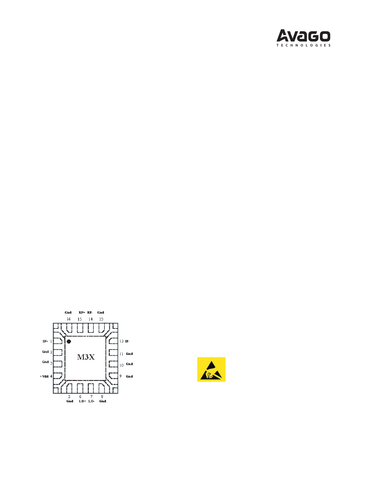
Pin Connections and Package Marking
Features
DC = 5V @ 26 mA (Typ.)
RF = 1.91 GHz, PinRF = -10 dBm;
LO = 1.7 GHz, PinLO = -3 dBm;
IF = 210 MHz unlesss otherwise specified
Lead-free Option Available
High Linearity: 27 dBm IIP3
Conversion Loss: 6 dB typical
Wide band operation: 400-3500 MHz RF & LO input
DC – 300 MHz IF output
Fully differential or single ended operation
High P1dB: 9 dBm typical
Low current consumption: 5V@ 26 mA typical
Excellent uniformity in product specifications
Small LPCC 3.0 x 3.0 x 0.75 mm package
MTTF > 300 years[1]
MSL-1 and lead-free
Tape-and-Reel packaging option available
Applications
Frequency up/down converter for base station radio
card, microwave link transceiver, and MMDS
Modulation and demodulation for receiver and
transmitter
General purpose resistive FET mixer for other high
linearity applications
Notes:
1. Refer to reliability datasheet for detailed MTTF data.
2. Conform to JEDEC reference outline MO229 for DRP-N
Notes:
Package marking provides orientation andidentification
“M3” = Device Code
“X” = Month code indicates the month of manufacture
Attention: Observe precautions for
handling electrostatic sensitive devices.
ESD Machine Model (Class A)
ESD Human Body Model (Class 1A)
Refer to Avago Application Note A004R:
Electrostatic Discharge Damage and Control.
1 page 
IAM-92516 Typical Performance, continued
DC = 5V @ 26 mA, RF =1.91 GHz, PinRF = -10 dBm; LO = 1.7 GHz, PinLO = -3 dBm, IF = 210 MHz unless otherwise specified
-22
-24
-26
-28
-30
-32
-34
-36
-38
-40 -20C
-40C
-42 +25C
-44 +85C
-46
-10 -9 -8 -7 -6 -5 -4 -3 -2 -1 0 1 2 3 4 5
LO POWER (dBm)
Figure 10. LO-RF Isolation vs LO Power Over
Temperature.
-30
-31
-32
-33
-34
-35
-36
-37
-20C
-38 -40C
-39
+25C
+85C
-40
-10 -9 -8 -7 -6 -5 -4 -3 -2 -1 0 1 2 3 4 5
LO POWER (dBm)
Figure 11. RF-IF Isolation vs LO Power Over
Temperature.
0
-2
-4
-6
-8
-10
-12
-14
-16
-18
-20
0 0.5 1 1.5 2 2.5 3 3.5 4 4.5 5 5.5 6
FREQUENCY (GHz)
Figure 12. RF Return Loss vs Frequency.
0
-5
-10
-15
-20
-25
-30
0 0.5 1 1.5 2 2.5 3 3.5 4 4.5 5 5.5 6
FREQUENCY (GHz)
Figure 13. LO Return Loss vs Frequency.
0
-2
-4
-6
-8
-10
-12
-14
-16
-18
-20
-22
-24
50 100 150 200 250 300 350 400 450 500
FREQUENCY (MHz)
Figure 14. IF Return Loss vs Frequency.
LO Harmonics (nLO)
01 2 3 4 5
0
—0
18.5 12.9 11.6
5.8
1 19.5 0
51.3 60.6 42.8 55.2
2 39.9 67.3 56.6 78.3 64.7 87.2
3 51.2 >90 >90 >90 >90 >90
4 68.9 >90 >90 >90 >90 >90
5 >90 >90 >90 >90 >90 >90
Harmonic Intermodulation Suppression[10 ]
Note:
10. Test Conditions of Harmonic Intermodulation Suppression:
a) RF =1.91 GHz @-10 dBm and LO =1.7 GHz @-3 dBm.
b) RF harmonics and intermodulation products are referenced to a desired signal produced
by frequency IF = 210 MHz.
c) LO Harmonics are referenced to the -3 dBm LO drive signal.
5
5 Page | ||
| Páginas | Total 7 Páginas | |
| PDF Descargar | [ Datasheet IAM-92516.PDF ] | |
Hoja de datos destacado
| Número de pieza | Descripción | Fabricantes |
| IAM-92516 | High Linearity GaAs FET Mixer | Hewlett-Packard |
| IAM-92516 | High Linearity GaAs FET Mixer | AVAGO |
| Número de pieza | Descripción | Fabricantes |
| SLA6805M | High Voltage 3 phase Motor Driver IC. |
Sanken |
| SDC1742 | 12- and 14-Bit Hybrid Synchro / Resolver-to-Digital Converters. |
Analog Devices |
|
DataSheet.es es una pagina web que funciona como un repositorio de manuales o hoja de datos de muchos de los productos más populares, |
| DataSheet.es | 2020 | Privacy Policy | Contacto | Buscar |