|
|
|
PDF FGA20S125P Data sheet ( Hoja de datos )
| Número de pieza | FGA20S125P | |
| Descripción | IGBT | |
| Fabricantes | Fairchild Semiconductor | |
| Logotipo | ||
Hay una vista previa y un enlace de descarga de FGA20S125P (archivo pdf) en la parte inferior de esta página. Total 9 Páginas | ||
|
No Preview Available !
November 2014
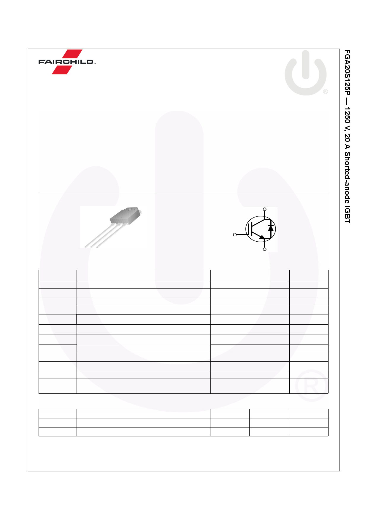
FGA20S125P
1250 V, 20 A Shorted-anode IGBT
Features
• High Speed Switching
• Low Saturation Voltage: VCE(sat) = 2.0 V @ IC = 20 A
• High Input Impedance
• RoHS Compliant
Applications
• Induction Heating, Microwave oven
General Description
Using advanced field stop trench and shorted anode technol-
ogy, Fairchild’s shorted-anode trench IGBTs offer superior con-
duction and switching performances for soft switching
applications. The device can operate in parallel configuration
with exceptional avalanche capability. This device is designed
for induction heating and microwave oven.
C
GCE
TO-3PN
Absolute Maximum Ratings TC = 25°C unless otherwise noted
Symbol
Description
VCES
VGES
IC
ICM (1)
Collector to Emitter Voltage
Gate to Emitter Voltage
Collector Current
Collector Current
Pulsed Collector Current
@ TC = 25oC
@ TC = 100oC
IF
Diode Continuous Forward Current
@ TC = 25oC
IF
Diode Continuous Forward Current
@ TC = 100oC
PD
Maximum Power Dissipation
Maximum Power Dissipation
@ TC = 25oC
@ TC = 100oC
TJ Operating Junction Temperature
Tstg Storage Temperature Range
TL
Maximum Lead Temp. for soldering
Purposes, 1/8” from case for 5 seconds
Thermal Characteristics
Symbol
RθJC(IGBT)
RθJA
Parameter
Thermal Resistance, Junction to Case
Thermal Resistance, Junction to Ambient
Notes:
1: Limited by Tjmax
G
E
FGA20S125P_SN00336
1250
±25
40
20
60
40
20
250
125
-55 to +175
-55 to +175
300
Typ.
--
--
Max.
0.6
40
Unit
V
V
A
A
A
A
A
W
W
oC
oC
oC
Unit
oC/W
oC/W
© 2014 Fairchild Semiconductor Corporation
FGA20S125P Rev. C1
1
www.fairchildsemi.com
1 page 
Typical Performance Characteristics
Figure 13. Turn-on Characteristics VS.
Collector Current
1000
Common Emitter
VGE = 15V, RG = 10Ω
TC = 25oC
TC = 175oC
tr
100
10
10
td(on)
20 30
Collector Current, IC [A]
40
Figure 14.Turn-off Characteristics VS.
Collector Current
1000
Common Emitter
VGE = 15V, RG = 10Ω
TC = 25oC
TC = 175oC
td(off)
tf
100
10 20 30 40
Collector Current, IC [A]
Figure 15. Switching Loss VS. Gate Resistance
10
Common Emitter
VCC = 600V, VGE = 15V
IC = 20A
TC = 25oC
TC = 175oC
Eoff Eon
1
Figure 16. Switching Loss VS. Collector Current
30
Common Emitter
VGE = 15V, RG = 10Ω
10k TC = 25oC
TC = 175oC
Eoff
1k
Eon
0.1
10
20 30 40 50 60
Gate Resistance, RG [Ω]
70
Figure 17. Turn off Switching SOA Characteristics
100
100
10
20 30
Collector Current, IC [A]
40
FIgure 18. Forward Characteristics
80
10
Safe Operating Area
VGE = 15V, TC = 175oC
1
1 10 100 1000 2000
Collector-Emitter Voltage, VCE [V]
10
1
0.1
0.5
TC = 25oC
TC = 175oC
1
Forward Voltage, VF [V]
2
© 2014 Fairchild Semiconductor Corporation
FGA20S125P Rev. C1
5
www.fairchildsemi.com
5 Page | ||
| Páginas | Total 9 Páginas | |
| PDF Descargar | [ Datasheet FGA20S125P.PDF ] | |
Hoja de datos destacado
| Número de pieza | Descripción | Fabricantes |
| FGA20S125P | IGBT | Fairchild Semiconductor |
| Número de pieza | Descripción | Fabricantes |
| SLA6805M | High Voltage 3 phase Motor Driver IC. |
Sanken |
| SDC1742 | 12- and 14-Bit Hybrid Synchro / Resolver-to-Digital Converters. |
Analog Devices |
|
DataSheet.es es una pagina web que funciona como un repositorio de manuales o hoja de datos de muchos de los productos más populares, |
| DataSheet.es | 2020 | Privacy Policy | Contacto | Buscar |