|
|
|
PDF SN7101P Data sheet ( Hoja de datos )
| Número de pieza | SN7101P | |
| Descripción | Voltage and Current Controller | |
| Fabricantes | AUK | |
| Logotipo | ||
Hay una vista previa y un enlace de descarga de SN7101P (archivo pdf) en la parte inferior de esta página. Total 10 Páginas | ||
|
No Preview Available !
Semiconductor
http:// www.auk.co.kr
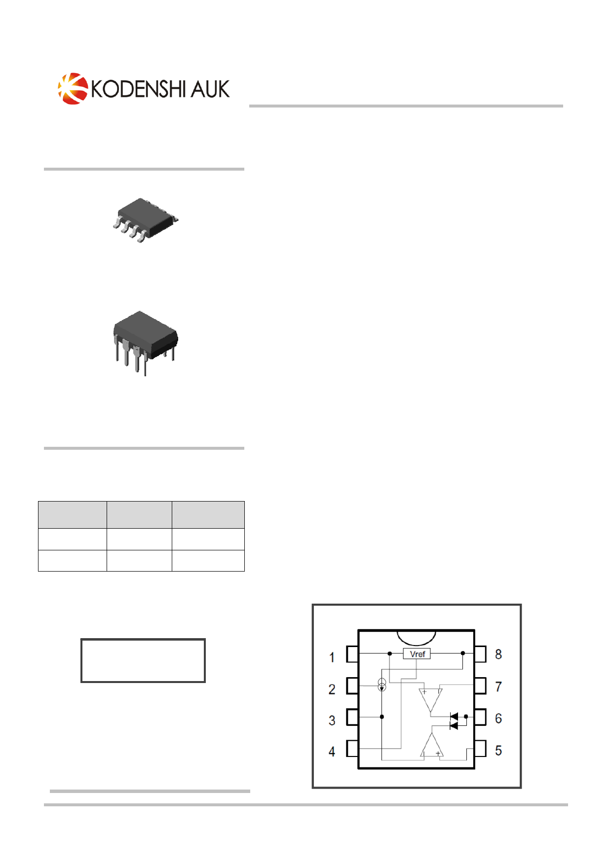
SOP-8
SN7101/P
Voltage and Current Controller
Description
The SN7101 is integrated a high stability band gap voltage reference,
two ORed operational amplifiers and a current source.
This IC compares the DC voltage and the current level at the output of
a switching power supply to an internal reference. It provides a feedback
through an Opto-coupler to the PWM controller IC in the primary side.
The controlled current generator can be used to modify the level of current
limitation by offsetting the information coming from the current sensing
resistor.
DIP-8
Features and Benefits
◈1.24V Series Voltage Reference with 10mA Output Current and
2.5% Precision
◈Two Operational Amplifiers with ORed Output And 1MHz Gain
Bandwidth
◈Built-in Current Generator with Enable/Disable Fucntion
◈Wide Range of Supply Voltage [ 4.5V to 32V ]
ORDERING INFORMATION
Product
SN7101
SN7101P
Marking
SN7101
SN7101
Package
SOP-8
DIP-8
▲ Marking Detail Information
Application
◈ Battery chargers
◈ AC to DC Power Supply
Block Diagram
SN7101(①)
YYWW(②)
① Device Code
② Week Code
Dec, 2011 REV. 00
KSD-I7F019-000
1
1 page 
SN7101/P
◈ Typical application circuit
Secondary Block
D2
C1
D1
C2
Photo
D io de
R2 R1
C3
1
V re f
2 Csen
3 C rref
4 GND
Vcc 8
R9
V rin 7
O utput
C rin
C4
6
C5
5
R3
R4
R5
R7
R8
C6
R6
COMPONENTS CALCULATIONS
The voltage control is given by the choice of the resistor bridge R6/R7 (and the trimmer R8)
Vref = R6/(R6+R7)xVout
where Vref = 1.24V
The current control is given by the choice of the voltage drop through the sense resistor R5 (to be linked to the
nominal current of the application) and by the value of the sense resistor itself.
For medium currents (< 1A), a good value for the voltage drop through R5 can be Vsense = 200mV
(dissipation < 200mW). The resistor bridge R2/R3 should be chosen following
Vsense = R3/(R2+R3)xVref
The total value of the resistor bridge should be in the range of the kin order to ensure a proper charge for the
voltage reference(in the range of themA).
To set the current limit, the senseresistorR5should be chosen following
Ilim = Vsense/R5
The internal current generator (Isce) can be used to offset the current limitation with a lower value.
This current generator is activated by connecting pin 2 to ground. It is inhibited if pin 2 is connected
to the positive rail via the pull up resistor R1. The current offset is given by the choice of the
resistor R4. If Ilim1 is the current limit calculated in the previous paragraph, and Ilim2 is the current limit that is to
be set when pin 2 is connected to ground, R4 should be chosen following
R4 = (Vsense - Ilim2xR5)/Isce
Dec, 2011 REV. 00
KSD-I7F019-000
5
5 Page | ||
| Páginas | Total 10 Páginas | |
| PDF Descargar | [ Datasheet SN7101P.PDF ] | |
Hoja de datos destacado
| Número de pieza | Descripción | Fabricantes |
| SN7101 | Voltage and Current Controller | AUK |
| SN7101P | Voltage and Current Controller | AUK |
| Número de pieza | Descripción | Fabricantes |
| SLA6805M | High Voltage 3 phase Motor Driver IC. |
Sanken |
| SDC1742 | 12- and 14-Bit Hybrid Synchro / Resolver-to-Digital Converters. |
Analog Devices |
|
DataSheet.es es una pagina web que funciona como un repositorio de manuales o hoja de datos de muchos de los productos más populares, |
| DataSheet.es | 2020 | Privacy Policy | Contacto | Buscar |