|
|
|
PDF MIC2072 Data sheet ( Hoja de datos )
| Número de pieza | MIC2072 | |
| Descripción | USB Power Controller | |
| Fabricantes | Micrel Semiconductor | |
| Logotipo | ||
Hay una vista previa y un enlace de descarga de MIC2072 (archivo pdf) en la parte inferior de esta página. Total 16 Páginas | ||
|
No Preview Available !
MIC2012
MIC2012/MIC2072
USB Power Controller
Micrel
General Description
The MIC2012 is a dual channel USB power switch designed to
support the power distribution requirements for USB Wakeup
from the ACPI S3 state. The MIC2012 will directly switch its
two outputs between a 5V main supply and a 5V auxiliary
supply normally provided in ATX style power supplies.
The MIC2012 will adjust its current-limit threshold according
to the ACPI state it is in. In the normal active S0 state the cur-
rent-limit is set at 500mA minimum per channel satisfying the
USB continuous output current specification. In the S3 state
the current-limit can be reduced to only 100mA per channel
to minimize the current that is supplied by the auxiliary supply
thereby ensuring that voltage regulation is maintained even
during fault conditions.
The MIC2012 provides make-before-break switching to ensure
glitch-free transitions between the S3 and S0 states. Each
channel is also thermally isolated from the other so that a
fault in one channel does not effect the other. FAULT status
output signals are also provided indicating overcurrent and
thermal shutdown conditions.
The MIC2072 option latches the output off upon detecting
an overcurrent condition for more than 5ms minimum. The
output can be reset by either toggling the EN inputs of the
MIC2072-1, -2 or by removing the load. Latching the output
off provides a circuit breaker mode of operation which reduces
power consumption during fault conditions.
Features
• Compliant to USB power distribution specifications
• UL Recognized Component
• Two completely independent switches
• Integrated switching matrix supports ACPI S0/S3 state
transitions without external FET circuits
• Make-before-break switching ensures glitch-free
transitions
• No back-feed of auxiliary supply onto main supply dur-
ing standby mode
• Bi-level current-limit preserves auxiliary supply voltage
regulation in standby mode
• Thermally isolated channels
• Thermal shutdown protection
• Fault status outputs with filter prevents false assertions
during hot-plug events
• Latched thermal shutdown options with auto-reset
(MIC2072)
• Undervoltage lockout
Applications
• Desktop PCs
• Notebook PCs
• Notebook Docking stations
• LAN Servers
• PC Motherboards
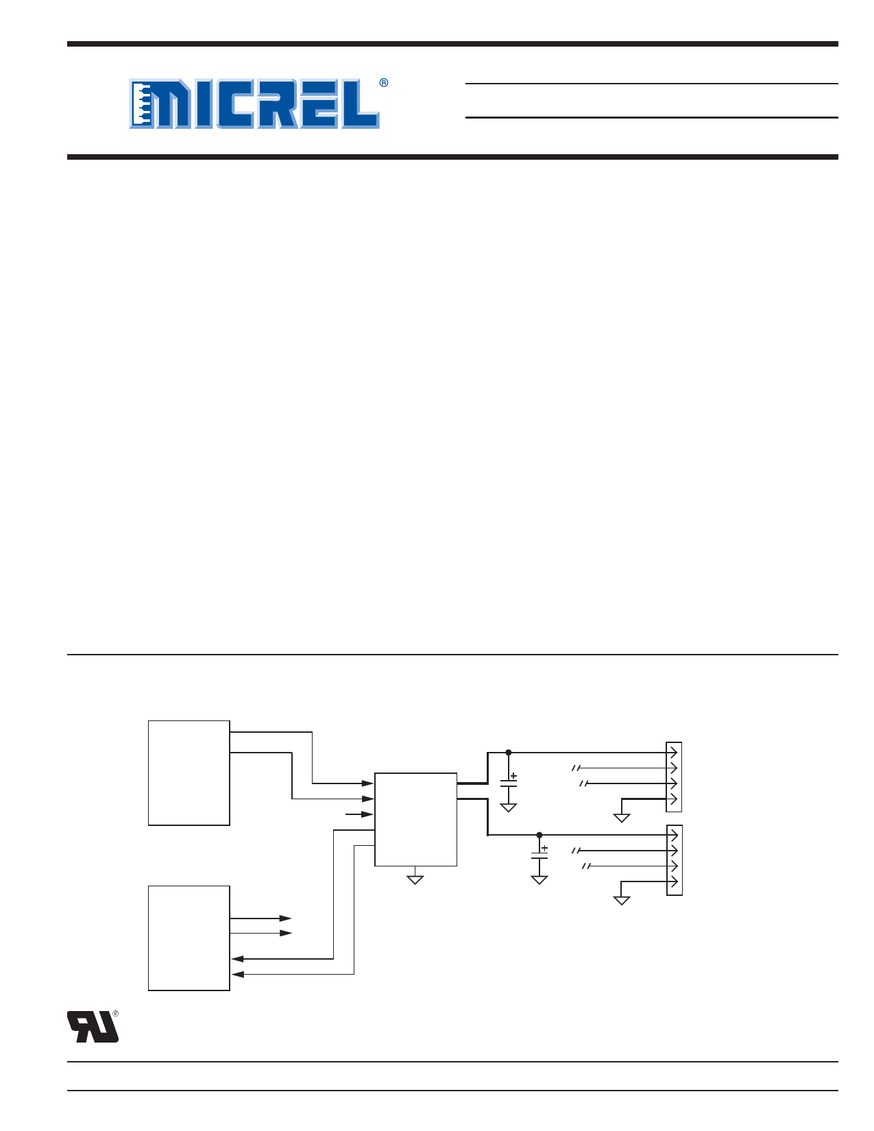
Typical Application
ATX Power Supply
5V MAIN
5V STANDBY
S3 Control
82801AA or Equivalent
SLP S3#
SLP S5#
OC0
OC1
Overcurrent Port 1
Overcurrent Port 1
MIC2012P
MAIN OUT1
AUX OUT2
S3#
FAULT1#
FAULT2#
GND
100F
100F
VBUS
D+
D–
GND
VBUS
D+
D–
GND
Downstream
USB
Port 1
Downstream
USB
Port 2
Figure 1. USB Wakeup with Control Input
UL Recognized Component
Micrel, Inc. • 2180 Fortune Drive • San Jose, CA 95131 • USA • tel + 1 (408) 944-0800 • fax + 1 (408) 474-1000 • http://www.micrel.com
January 2005
1
MIC2012/2072
1 page 
MIC2012
Micrel
Symbol
VTH LATCH
VOL
VOH
TH
TS
tDLY
tOC
tON(MAIN)
tOFF(MAIN)
tr(MAIN)
tf(MAIN)
tON(AUX)
tOFF(AUX)
tr(AUX)
tf(AUX)
tXMA
tXAM
Parameter
Latch Reset Threshold
(MIC2072, MIC2072-x only)
Minimum Output Slew Rate
to Reset Latch
(MIC2072, MIC2072-x only), Note 6
Overtemperature Threshold
FAULT Output Low Voltage
FAULT Output High Voltage
(MIC2012-1P,-2P),(MIC2072-1P,-2P)
FAULT Output Off Current
(Not Applicable to 'P' Options)
MAIN to S3# Hold Time, Note 6
MAIN to S3# Set-up Time, Note 6
FAULT Delay Filter Response Time
(Overcurrent only), Note 7
Overcurrent Response Time
MAIN Output Turn-On Time
MAIN Output Turn-Off Time
(MIC20x2-x only)
MAIN Output Rise Time
MAIN Output Fall Time
(MIC20x2-x only)
AUX Output Turn-On Time
AUX Output Turn-Off Time
(MIC20x2-x only)
AUX Output Rise Time
AUX Output Fall Time
(MIC20x2-x only)
MAIN to AUX
Cross Conduction Time, Note 8
AUX to MAIN
Cross Conduction Time, Note 8
Condition
VOUT Rising
TJ increasing, single channel
TJ decreasing, single channel
TJ increasing, both channels
TJ decreasing, both channels
IFAULT = 5mA
IFAULT = –20µA
VFAULT = 5V
Figure 5
Figure 5
Output shorted to ground, Figure 4
Output shorted to ground, Figure 4
MAIN output
AUX output
RL = 10Ω, CL = 1µF, Figure 3
RL = 10Ω, CL = 1µF, Figure 3
RL = 10Ω, CL = 1µF, Figure 3
RL = 10Ω, CL = 1µF, Figure 3
RL = 50Ω, CL = 1µF, Figure 3
RL = 50Ω, CL = 1µF, Figure 3
RL = 50Ω, CL = 1µF, Figure 3
RL = 50Ω, CL = 1µF, Figure 3
S3# transition to 0
S3# transition to 1
Min Typ Max Units
1.95 V
0.4 V/s
140 °C
120 °C
160 °C
150 °C
0.2 V
4V
0.2 10 µA
5 ms
0 ms
5 10 20 ms
2 µs
2 µs
2 ms
35 µs
2 ms
32 µs
0.6 ms
120 µs
0.5 ms
115 µs
5 7.5 ms
5 7.5 ms
Note 1.
Note 2.
Note 3.
Note 4.
Note 5.
Note 6.
Note 7.
Note 8.
Exceeding the absolute maximum rating may damage the device.
The device is not guaranteed to function outside its operating rating.
Devices are ESD sensitive. Handling precautions recommended. Human body model, 1.5k in series with 100pF.
All voltages are referenced to ground.
For MIC20x2-1(P) OFF occurs when VEN < 0.8V and ON occurs when VEN > 2.4V. For MIC20x2-2(P) OFF occurs when VEN > 2.4V and ON
occurs when VEN < 0.8V.
Guaranteed by design. Not production tested.
Assumes only one channel in current-limit. Delay circuitry is shared among channels so it is possible for tDLY to be 40ms max if one channel
enters current-limit as the other is about to time-out.
Cross conduction time is the duration in which both MAIN and AUX internal switches are on subsequent to S3# transitioning.
January 2005
5
MIC2012/2072
5 Page 
MIC2012
AUX Turn-On Response
VAUX =5V
VMAIN = S3# = 0V
EN toggles from [OFF] to [ON]
RLOAD = 50
CLOAD = 1F
TIME (100s/div)
Turn-On from S3# to AUX
Micrel
AUX Turn-Off Response
VAUX =5V
VMAIN = S3# = 0V
EN toggles from [ON] to [OFF]
RLOAD = 50
CLOAD = 1F
TIME (100s/div)
Turn-Off from AUX to S3#
VAUX =5V, VMAIN = 0V
EN = [ON]
S3# toggles from [HI] to [LOW]
RLOAD = 50
CLOAD = 1F
TIME (100s/div)
Main Inrush Current into CLOAD
VMAIN = VAUX = 5V
S3# = 5V
EN toggles from [OFF] to [ON]
RLOAD = OPEN
CLOAD = 10F, 100F, 560F
CL = 560F
CL = 100F
CL = 10F
TIME (500s/div)
VAUX =5V, VMAIN = 0V
S3# toggles from [LO] to [HI]
EN = [ON]
RLOAD = 50
CLOAD = 1F
TIME (1ms/div)
Main-Ramped to Short by MOSFET
VMAIN = VAUX =5V
S3# = 5V, EN = [ON]
CLOAD = 1F
1.4A
RLOAD toggles from > 1k to <0.5
TIME (50ms/div)
January 2005
11
MIC2012/2072
11 Page | ||
| Páginas | Total 16 Páginas | |
| PDF Descargar | [ Datasheet MIC2072.PDF ] | |
Hoja de datos destacado
| Número de pieza | Descripción | Fabricantes |
| MIC2070 | USB Power Controller | Micrel Semiconductor |
| MIC2072 | USB Power Controller | Micrel Semiconductor |
| MIC2075 | Single-Channel Power Distribution Switch MM8 | Micrel Semiconductor |
| MIC2076 | Dual-Channel Power Distribution Switch | Micrel Semiconductor |
| Número de pieza | Descripción | Fabricantes |
| SLA6805M | High Voltage 3 phase Motor Driver IC. |
Sanken |
| SDC1742 | 12- and 14-Bit Hybrid Synchro / Resolver-to-Digital Converters. |
Analog Devices |
|
DataSheet.es es una pagina web que funciona como un repositorio de manuales o hoja de datos de muchos de los productos más populares, |
| DataSheet.es | 2020 | Privacy Policy | Contacto | Buscar |