|
|
|
PDF Si7949DP Data sheet ( Hoja de datos )
| Número de pieza | Si7949DP | |
| Descripción | Dual P-Channel 60-V (D-S) MOSFET | |
| Fabricantes | Vishay | |
| Logotipo | ||
Hay una vista previa y un enlace de descarga de Si7949DP (archivo pdf) en la parte inferior de esta página. Total 12 Páginas | ||
|
No Preview Available !
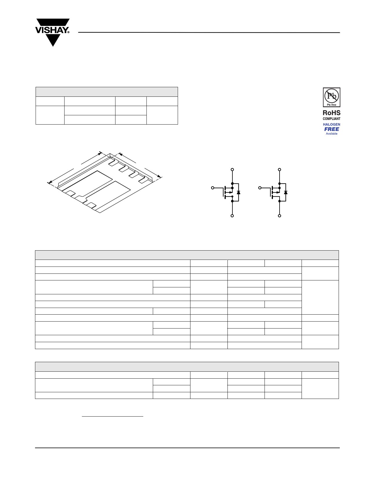
Dual P-Channel 60-V (D-S) MOSFET
Si7949DP
Vishay Siliconix
PRODUCT SUMMARY
VDS (V)
RDS(on) (Ω)
0.064 at VGS = - 10 V
- 60
0.080 at VGS = - 4.5 V
ID (A)
-5
- 4.5
Qg (Typ.)
26
FEATURES
• Halogen-free According to IEC 61249-2-21
Available
• TrenchFET® Power MOSFET
• New Low Thermal Resistance PowerPAK®
Package with Low 1.07 mm Profile
PowerPAK SO-8
6.15 mm
S1
1
G1
2
5.15 mm
S2
3 G2
4
D1
8
D1
7
D2
6 D2
5
Bottom View
Ordering Information: Si7949DP-T1-E3 (Lead (Pb)-free)
Si7949DP-T1-GE3 (Lead (Pb)-free and Halogen-free)
S1 S2
G1 G2
D1
P-Channel MOSFET
D2
P-Channel MOSFET
ABSOLUTE MAXIMUM RATINGS TA = 25 °C, unless otherwise noted
Parameter
Symbol
10 s Steady State
Drain-Source Voltage
Gate-Source Voltage
Continuous Drain Current (TJ = 150 °C)a
Pulsed Drain Current
Continuous Source Current (Diode Conduction)a
Avalanche Current
Single Pulse Avalanche Energy
Maximum Power Dissipationa
Operating Junction and Storage Temperature Range
Soldering Recommendations (Peak Temperature)b,c
TA = 25 °C
TA = 70 °C
L = 0.1 mH
TA = 25 °C
TA = 70 °C
VDS
VGS
ID
IDM
IS
IAS
EAS
PD
TJ, Tstg
- 60
± 20
- 5 - 3.2
- 4 - 2.6
- 25
- 2.9
- 1.2
22
24.2
3.5 1.5
2.2 0.94
- 55 to 150
260
Unit
V
A
mJ
W
°C
THERMAL RESISTANCE RATINGS
Parameter
Symbol
Typical
Maximum
Unit
Maximum Junction-to-Ambienta
t ≤ 10 s
Steady State
RthJA
27
60
36
85 °C/W
Maximum Junction-to-Case (Drain)
Steady State
RthJC
3.3
4.3
Notes:
a. Surface Mounted on 1" x 1" FR4 board.
b. See Solder Profile (www.vishay.com/ppg?73257). The PowerPAK SO-8 is a leadless package. The end of the lead terminal is exposed copper
(not plated) as a result of the singulation process in manufacturing. A solder fillet at the exposed copper tip cannot be guaranteed and is not
required to ensure adequate bottom side solder interconnection.
c. Rework Conditions: manual soldering with a soldering iron is not recommended for leadless components.
Document Number: 73130
S09-0223-Rev. B, 09-Feb-09
www.vishay.com
1
1 page 
TYPICAL CHARACTERISTICS 25 °C, unless otherwise noted
2
1
Duty Cycle = 0.5
0.2
0.1
0.1
0.05
0.02
Single Pulse
Si7949DP
Vishay Siliconix
0.01
10-4
10-3
10-2
10-1
Square Wave Pulse Duration (s)
Normalized Thermal Transient Impedance, Junction-to-Case
1
Vishay Siliconix maintains worldwide manufacturing capability. Products may be manufactured at one of several qualified locations. Reliability data for Silicon
Technology and Package Reliability represent a composite of all qualified locations. For related documents such as package/tape drawings, part marking, and
reliability data, see www.vishay.com/ppg?73130.
Document Number: 73130
S09-0223-Rev. B, 09-Feb-09
www.vishay.com
5
5 Page 
Application Note 826
Vishay Siliconix
RECOMMENDED MINIMUM PADS FOR PowerPAK® SO-8 Dual
0.024
(0.61)
0.026
(0.66)
0.260
(6.61)
0.150
(3.81)
0.024
(0.61)
0.050
(1.27)
0.032
(0.82)
Return to Index
Return to Index
Recommended Minimum Pads
Dimensions in Inches/(mm)
0.040
(1.02)
www.vishay.com
16
Document Number: 72600
Revision: 21-Jan-08
11 Page | ||
| Páginas | Total 12 Páginas | |
| PDF Descargar | [ Datasheet Si7949DP.PDF ] | |
Hoja de datos destacado
| Número de pieza | Descripción | Fabricantes |
| Si7949DP | Dual P-Channel 60-V (D-S) MOSFET | Vishay |
| Número de pieza | Descripción | Fabricantes |
| SLA6805M | High Voltage 3 phase Motor Driver IC. |
Sanken |
| SDC1742 | 12- and 14-Bit Hybrid Synchro / Resolver-to-Digital Converters. |
Analog Devices |
|
DataSheet.es es una pagina web que funciona como un repositorio de manuales o hoja de datos de muchos de los productos más populares, |
| DataSheet.es | 2020 | Privacy Policy | Contacto | Buscar |