|
|
|
PDF C3M0065100K Data sheet ( Hoja de datos )
| Número de pieza | C3M0065100K | |
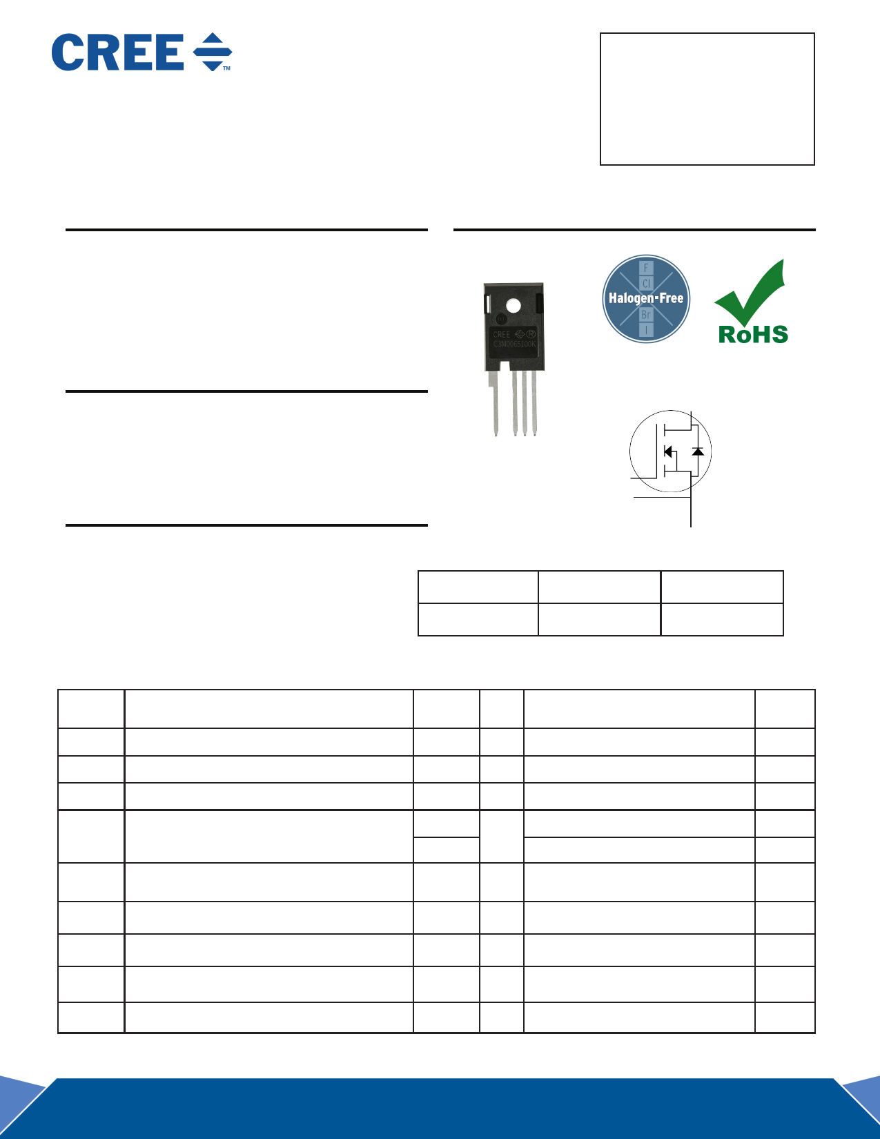
| Descripción | Silicon Carbide Power MOSFET | |
| Fabricantes | Cree | |
| Logotipo | ||
Hay una vista previa y un enlace de descarga de C3M0065100K (archivo pdf) en la parte inferior de esta página. Total 11 Páginas | ||
|
No Preview Available !
VDS 1000 V
C3M0065100K
ID @ 25˚C
35 A
Silicon Carbide Power MOSFET
TM
C3M MOSFET Technology
RDS(on) 65 mΩ
N-Channel Enhancement Mode
Features
Package
• New C3MTM SiC MOSFET technology
• Optimized package with separate driver source pin
• 8mm of creepage distance between drain and source
• High blocking voltage with low on-resistance
• High-speed switching with low capacitances
•
•
Fast intrinsic diode with low reverse recovery (Qrr)
Halogen free, RoHS compliant
Benefits
• Reduce switching losses and minimize gate ringing
• Higher system efficiency
• Reduce cooling requirements
• Increase power density
• Increase system switching frequency
Applications
• Renewable energy
• EV battery chargers
• High voltage DC/DC converters
• Switch Mode Power Supplies
TAB
Drain
1 234
D SSG
Drain
(Pin 1, TAB)
Gate
(Pin 4)
Driver
Source
(Pin 3)
Power
Source
(Pin 2)
Part Number
C3M0065100K
Package
TO 247-4
Marking
C3M0065100K
Maximum Ratings (TC = 25 ˚C unless otherwise specified)
Symbol
Parameter
Value
VDSmax
VGSmax
VGSop
Drain - Source Voltage
Gate - Source Voltage (dynamic)
Gate - Source Voltage (static)
ID Continuous Drain Current
1000
-8/+19
-4/+15
35
22.5
ID(pulse) Pulsed Drain Current
90
EAS Avalanche energy, Single pulse
PD Power Dissipation
TJ , Tstg Operating Junction and Storage Temperature
TL Solder Temperature
Note (1): When using MOSFET Body Diode VGSmax = -4V/+19V
Note (2): MOSFET can also safely operate at 0/+15 V
110
113.5
-55 to
+150
260
Unit Test Conditions
V VGS = 0 V, ID = 100 μA
V AC (f >1 Hz)
V Static
VGS = 15 V, TC = 25˚C
A
VGS = 15 V, TC = 100˚C
A Pulse width tP limited by Tjmax
mJ ID = 22A, VDD = 50V
W TC=25˚C, TJ = 150 ˚C
˚C
˚C 1.6mm (0.063”) from case for 10s
Note
Note: 1
Note: 2
Fig. 19
Fig. 22
Fig. 20
1 C3M0065100K Rev. -, 09-2016
1 page 
Typical Performance
-8 -7 -6 -5 -4 -3 -2 -1 0
0
VGS = 0 V
VGS = 5 V
VGS = 10 V
VGS = 15 V
-10
-20
-30
-40
-50
Drain-Source Voltage VDS (V)
Conditions:
TJ = -55 °C
tp < 200 µs
-60
-70
-80
Figure 13. 3rd Quadrant Characteristic at -55 ºC
-8 -7 -6 -5 -4 -3 -2 -1 0
0
VGS = 0 V
-10
-20
VGS = 5 V
VGS = 10 V
VGS = 15 V
-30
-40
-50
Drain-Source Voltage VDS (V)
Conditions:
TJ = 150 °C
tp < 200 µs
-60
-70
-80
Figure 15. 3rd Quadrant Characteristic at 150 ºC
10000
1000
Conditions:
TJ = 25 °C
VAC = 25 mV
f = 1 MHz
Ciss
Coss
100
10 Crss
1
0 50 100 150
Drain-Source Voltage, VDS (V)
Figure 17. Capacitances vs. Drain-Source
Voltage (0 - 200V)
200
-8 -7 -6 -5 -4 -3 -2 -1 0
0
VGS = 0 V
VGS = 5 V
-10
-20
VGS = 10 V
VGS = 15 V
-30
-40
-50
Drain-Source Voltage VDS (V)
Conditions:
TJ = 25 °C
tp < 200 µs
-60
-70
-80
Figure 14. 3rd Quadrant Characteristic at 25 ºC
35
30
25
20
15
10
5
0
0
200 400 600 800
Drain to Source Voltage, VDS (V)
1000
10000
1000
Figure 16. Output Capacitor Stored Energy
Conditions:
TJ = 25 °C
VAC = 25 mV
f = 1 MHz
Ciss
100 Coss
10
Crss
1
0 200 400 600 800
Drain-Source Voltage, VDS (V)
Figure 18. Capacitances vs. Drain-Source
Voltage (0 - 1000V)
1000
5 C3M0065100K Rev. -, 09-2016
5 Page 
Notes
• RoHS Compliance
The levels of RoHS restricted materials in this product are below the maximum concentration values (also referred to as the
threshold limits) permitted for such substances, or are used in an exempted application, in accordance with EU Directive 2011/65/
EC (RoHS2), as implemented January 2, 2013. RoHS Declarations for this product can be obtained from your Cree representative or
from the Product Documentation sections of www.cree.com.
• REACh Compliance
REACh substances of high concern (SVHCs) information is available for this product. Since the European Chemical Agency (ECHA)
has published notice of their intent to frequently revise the SVHC listing for the foreseeable future,please contact a Cree represen-
tative to insure you get the most up-to-date REACh SVHC Declaration. REACh banned substance information (REACh Article 67) is
also available upon request.
• This product has not been designed or tested for use in, and is not intended for use in, applications implanted into the human body
nor in applications in which failure of the product could lead to death, personal injury or property damage, including but not limited
to equipment used in the operation of nuclear facilities, life-support machines, cardiac defibrillators or similar emergency medical
equipment, aircraft navigation or communication or control systems, air traffic control systems.
Related Links
• SPICE Models: http://wolfspeed.com/power/tools-and-support
• SiC MOSFET Isolated Gate Driver reference design: http://wolfspeed.com/power/tools-and-support
• SiC MOSFET Evaluation Board: http://wolfspeed.com/power/tools-and-support
Copyright © 2016 Cree, Inc. All rights reserved.
The information in this document is subject to change without notice.
Cree, the Cree logo, and Zero Recovery are registered trademarks of Cree, Inc.
11 C3M0065100K Rev -, 09-2016
Cree, Inc.
4600 Silicon Drive
Durham, NC 27703
USA Tel: +1.919.313.5300
Fax: +1.919.313.5451
www.wolfspeed.com/power
11 Page | ||
| Páginas | Total 11 Páginas | |
| PDF Descargar | [ Datasheet C3M0065100K.PDF ] | |
Hoja de datos destacado
| Número de pieza | Descripción | Fabricantes |
| C3M0065100K | Silicon Carbide Power MOSFET | Cree |
| Número de pieza | Descripción | Fabricantes |
| SLA6805M | High Voltage 3 phase Motor Driver IC. |
Sanken |
| SDC1742 | 12- and 14-Bit Hybrid Synchro / Resolver-to-Digital Converters. |
Analog Devices |
|
DataSheet.es es una pagina web que funciona como un repositorio de manuales o hoja de datos de muchos de los productos más populares, |
| DataSheet.es | 2020 | Privacy Policy | Contacto | Buscar |