|
|
|
PDF IW1810 Data sheet ( Hoja de datos )
| Número de pieza | IW1810 | |
| Descripción | Off-Line Digital Green-Mode PWM Controller | |
| Fabricantes | iWatt | |
| Logotipo | ||
Hay una vista previa y un enlace de descarga de IW1810 (archivo pdf) en la parte inferior de esta página. Total 13 Páginas | ||
|
No Preview Available !
iW1810
Off-Line Digital Green-Mode PWM Controller
Integrated with Power BJT
1.0 Features
●● Primary-side feedback eliminates opto-isolators and
simplifies design
●● Internal 800-V bipolar junction transistor (BJT)
●● 64kHz PWM switching frequency
●● No-load power consumption < 100mW at 230Vac with
typical application circuit
●● Adaptive multi-mode PWM/PFM control improves
efficiency
●● Quasi-resonant operation for highest overall efficiency
●● EZ-EMI® design to easily meet global EMI standards
●● Dynamic BJT base drive current control
●● Very tight constant voltage and constant current
regulation with primary-side-only feedback
●● No external compensation components required
●● Complies with EPA 2.0 energy-efficiency specifications
with ample margin
●● Low start-up current (8μA typical)
●● Built-in soft start
●● Built-in short circuit protection and output overvoltage
protection
●● Built-in current sense resistor short circuit protection
●● No audible noise over entire operating range
L
2.0 Description
The iW1810 is a high performance AC/DC power supply
control device which uses digital control technology to
build peak current mode PWM flyback power supplies.
This device includes an internal power BJT and operates in
quasi-resonant mode to provide high efficiency along with a
number of key built-in protection features while minimizing
the external component count, simplifying EMI design and
lowering the total bill of material cost. The iW1810 removes
the need for secondary feedback circuitry while achieving
excellent line and load regulation. It also eliminates the
need for loop compensation components while maintaining
stability over all operating conditions. Pulse-by-pulse
waveform analysis allows for a loop response that is much
faster than traditional solutions, resulting in improved
dynamic load response. The built-in power limit function
enables optimized transformer design in universal off-line
applications and allows for a wide input voltage range.
iWatt’s innovative proprietary technology ensures that
power supplies built with iW1810 can achieve both highest
average efficiency and less than 100 mW no-load power
consumption in a compact form factor.
3.0 Applications
●● Low-power AC/DC power supply for smart meters, motor
control and industrial applications
●● Linear AC/DC replacement
●● Low-power AC/DC LED driver
+
N
+ VOUT
GND
1C
U1
iW1810
E8
2C
4 VCC
ISENSE 7
VSENSE 6
GND 5
WARNING:
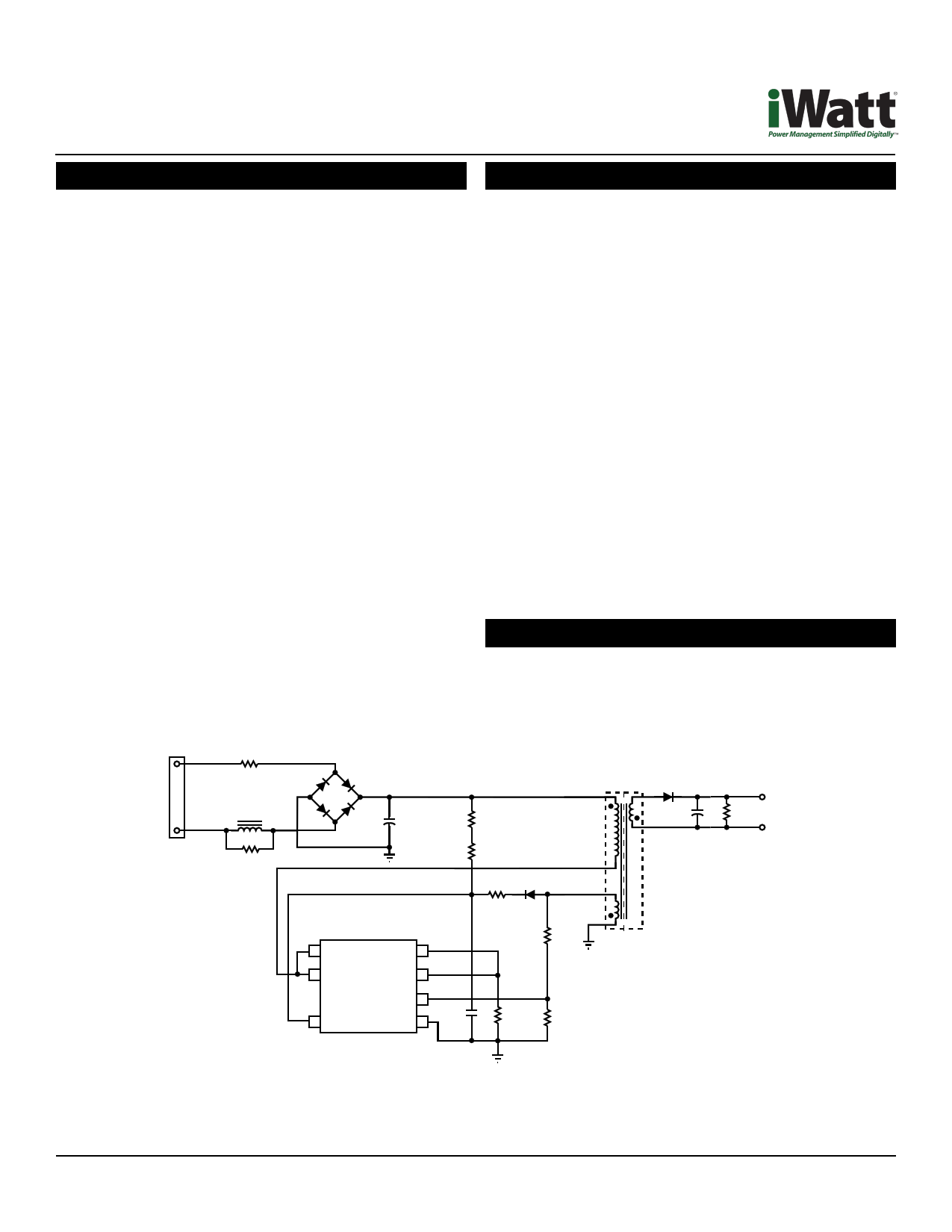
Figure 3.1: iW1810 Typical Application Circuit
The iW1810 is intended for high voltage AC/DC offline applications. Contact with live high voltage offline circuits
or improper use of components may cause lethal or life threatening injuries or property damage. Only qualified
professionals with safety training and proper precaution should operate with high voltage offline circuits.
Rev. 1.2
iW1810
April 6, 2012
Page 1
1 page 
iW1810
Off-Line Digital Green-Mode PWM Controller
Integrated with Power BJT
7.0 Electrical Characteristics (cont.)
VCC = 12V, -40°C ≤ TA ≤ +85°C
Parameter
BJT Section (Pin 1, Pin 2, and Pin 8)
Collector cutoff current
Symbol
ICB0
Test Conditions
VCB = 800V, IE = 0A
VCE = 800V, REB = 0Ω TA
= 25°C
Collector-Emitter cutoff current
ICES
VCE = 800V, REB = 0Ω TA
= 100°C
VCE = 500V, REB = 0Ω TA
= 25°C
DC Current Gain2
Collector-Base breakdown voltage
Collector-Emitter breakdown voltage
(Emitter and base shorted together)
hFE
VCB0
VCES
VCE = 5V, IC = 0.2A
VCE = 5V, IC = 0.3A
VCE = 5V, IC = 1mA
IC = 0.1mA
IC = 1mA, REB = 0Ω
Collector-Emitter sustain voltage
Collector-Emitter saturation voltage2
PWM switching frequency
VCEO(SUS)
VCE sat
fSW
IC = 1mA, LM = 25mH
IC = 0.1A, IB = 0.02 A
> 50% load
Min
15
10
10
800
800
500
Typ Max Unit
0.01 mA
0.01
0.02 mA
0.005
40
30
V
V
V
0.1 0.3
V
64 kHz
Notes:
1. These parameters are not 100% tested, guaranteed by design and characterization.
2. Impulse tP ≤ 300μs, duty cycle ≤ 2%
3. Operating frequency varies based on the load conditions, see Section 10.6 for more details.
Rev. 1.2
iW1810
April 6, 2012
Page 5
5 Page 
iW1810
Off-Line Digital Green-Mode PWM Controller
Integrated with Power BJT
10.11 Dynamic Base Current Control
One important feature of the iW1810 is that it directly drives
an internal BJT switching device with dynamic base current
control to optimize performance. The BJT base current
ranges from 10mA to 31mA, and is dynamically controlled
according to the power supply load change. The higher the
output power, the higher the base current. Specifically, the
base current is related to VIPK, as shown in Figure 10.5.
35
30
25
20
15
10
5
00 0.1 0.2 0.3 0.4 0.5 0.6 0.7 0.8 0.9 1.0 1.1
VIPK (V)
Figure 10.5: Base Drive Current vs. VIPK
10.12 Thermal Design
The iW1810 may be installed inside a small enclosure,
where space and air volumes are constrained. Under these
circumstances θJA (thermal resistance, junction to ambient)
measurements do not provide useful information for this
type of application. Hence we have also provided ψJB which
estimates the increase in die junction temperature relative to
the PCB surface temperature. Figure 10.6 shows the PCB
surface temperature is measured at the IC’s GND pin pad.
used to estimate the maximum junction temperature. For
a typical 3-W power supply, the power dissipation can be
around 500mW.
The output power table in Section 3.0 recommends
maximum practical continuous output power level be
achieved under the following conditions:
●● Typical 5V-output power supply designs with a Schottky
rectifier diode
●● Ambient temperature of 50°C for open frame and
adapter enclosure internal temperature of 60°C in a non-
ventilated environment
●● AC Input voltage is 85VAC at 47Hz
●● Minimum bulk capacitor voltage is 90V for open frame
and 70V for adapter
●● The iW1810 device is mounted on PCB with no special
enhancement for heatsinking and the emitter pin
temperature is kept below 90°C
Under a given power dissipation, reducing the GND,
emitter, and collector pin temperature reduces the junction
temperature. Generally, increasing the PCB area and
associated amount of copper trace reduces the junction
temperature. In particular, the power BJT is a power source
and therefore the PCB plating area attached to the two
collector pins and the emitter pin can be reasonably large to
gain the thermal benefits without violating the high voltage
creepage requirements if higher output power is desired.
Higher output power is also achievable if bulk capacitor
voltage is higher, design is for high line only, design
components temperature restriction limit is higher, ambient
temperature is lower, or extra metal piece/heat spreader is
attached to related pins or package.
BJT collector
ψJ-BJT
J
Collector pin
TJ
J ψJB
B
IC Die
PCB Top Copper Trace
GND pin
Printed Circuit Board
Note: For illustrative purposes only does not represent a correct pinout or size of chip
Figure 10.6: Thermal Resistance
The actual IC power dissipation is related to the power supply
application circuit, component selection, and operation
conditions. The maximum IC power dissipation should be
Rev. 1.2
iW1810
April 6, 2012
Page 11
11 Page | ||
| Páginas | Total 13 Páginas | |
| PDF Descargar | [ Datasheet IW1810.PDF ] | |
Hoja de datos destacado
| Número de pieza | Descripción | Fabricantes |
| IW1810 | Off-Line Digital Green-Mode PWM Controller | iWatt |
| IW1812 | Off-Line Digital Green-Mode PWM Controller | Dialog Semiconductor |
| IW1816 | Off-Line Digital Green-Mode PWM Controller | Dialog Semiconductor |
| Número de pieza | Descripción | Fabricantes |
| SLA6805M | High Voltage 3 phase Motor Driver IC. |
Sanken |
| SDC1742 | 12- and 14-Bit Hybrid Synchro / Resolver-to-Digital Converters. |
Analog Devices |
|
DataSheet.es es una pagina web que funciona como un repositorio de manuales o hoja de datos de muchos de los productos más populares, |
| DataSheet.es | 2020 | Privacy Policy | Contacto | Buscar |