|
|
|
PDF MAP3202 Data sheet ( Hoja de datos )
| Número de pieza | MAP3202 | |
| Descripción | High Efficiency Switch Mode LED Driver | |
| Fabricantes | MagnaChip | |
| Logotipo | ||
 1. Efficiency Switch Mode LED Driver Hay una vista previa y un enlace de descarga de MAP3202 (archivo pdf) en la parte inferior de esta página. Total 15 Páginas | ||
|
No Preview Available !
Confidential
Datasheet Version 1.1
Datasheet - MAP3202
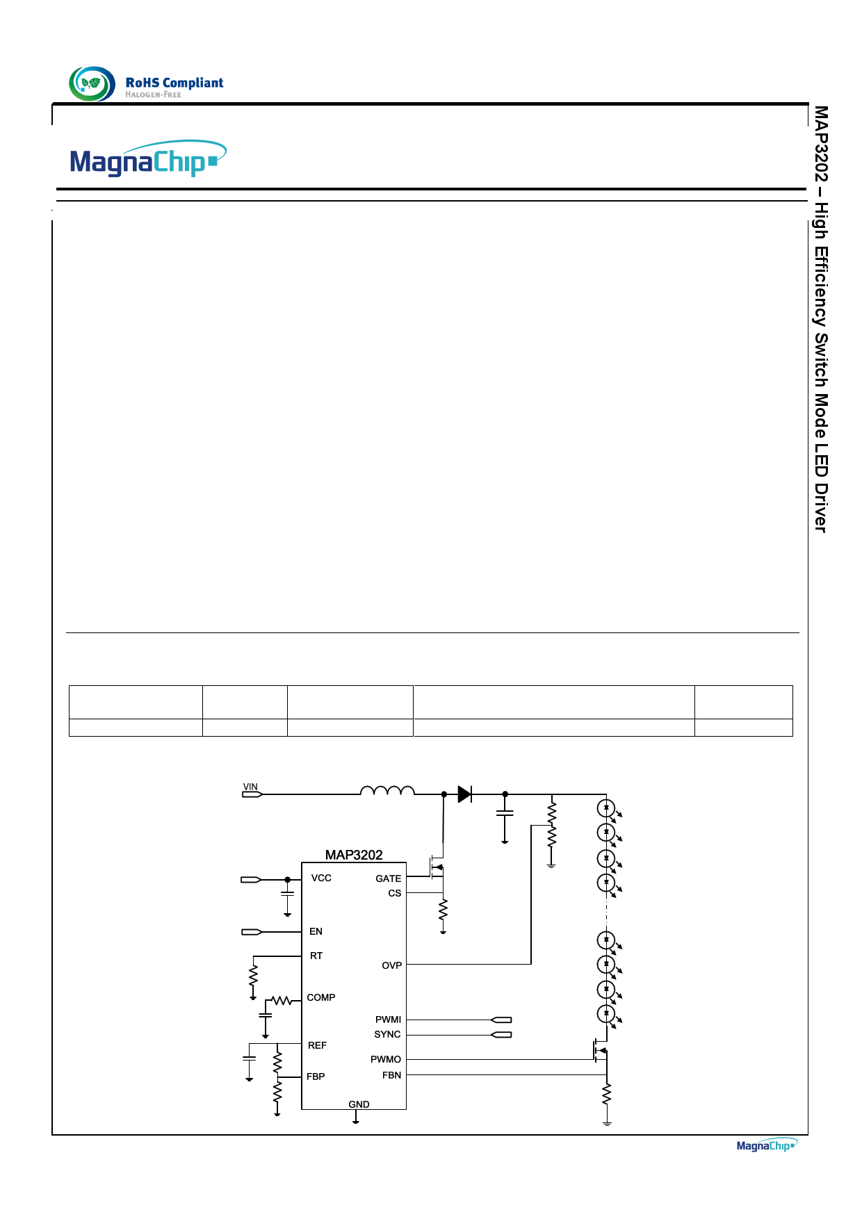
High Efficiency Switch Mode LED Driver
General Description
MAP3202 is a single channel high efficiency boost
type PWM driver with current mode control. It is
designed for high brightness LED driver optimized for
backlighting system for LCD module.
MAP3202 offers the function of accurate and fast LED
dimming control using PWM interface and external
dimming MOSFET.
MAP3202 has the over-voltage protection, the short-
current protection and UVLO, providing auto-restart
function.
Features
Wide input voltage range up to 18V
PWM Dimming
Current Mode Control Type
Synchronization to peer to peer
Internal Auto Restart Mode Protection
Programmable Output Over Voltage Protection
LED Short Current Protection
Boost switch current limit Protection
Package : SOIC-14 Pin
MAP3202 is available in SOIC-14 Pin package with
Halogen-free (fully RoHS compliant).
For more information, please contact local MagnaChip
sales office in world-wide or visit MagnaChip’s website
at www.magnachip.com.
Applications
High Brightness white LED backlighting for LCD
TVs and monitors
General LED lighting applications
Ordering Information
Part Number
MAP3202SIRH
Top
Marking
MAP3202
Ambient
Temperature Range
-40℃ to +85℃
Typical Application
Package
SOIC-14 Pin
RoHS Status
Halogen Free
March 2012
Page 1
1 page 
Confidential
Datasheet Version 1.1
Electrical Characteristics (continued)
VCC=12V, VPWMI=5V, Ta=25℃, unless otherwise specified
SYMBOL
PARAMETER
TEST CONDITION
Internal Transconductance Opamp
IBIAS Input Bias current
-
VOFFSET
Input Offset voltage
-
I_AMP_SOURCE AMP Source Current
VFBN=1V, VFBP=2V, VCOMP=1.5V
I_AMP_SINK
AMP Sink Current
VFBN=2V, VFBP=1V, VCOMP=1.5V
Oscillator
FOSC
Oscillator frequency
( 100KHz ~ 400KHz )
Ta=-40℃ ~ 85℃, RT=500㏀
Ta=25℃, RT=500㏀
Ta=-40℃ ~ 85℃, RT=123㏀
DMAX
Maximum duty cycle
-
Synchronizing ( External Input )
VIL_SYNC
SYNC Input voltage Low level
-
VIH_SYNC
TSYNC_MIN
SYNC Input voltage high level
SYNC minimum input pulse width(3)
-
VSYNC = 0V to 5V
MIN
-
-5
-
-
90
95
340
-
-
2
20
TSYNC_MAX
SYNC maximum input pulse width
VSYNC = 0V to 5V
-
PWM Input
VPWMI(LO)
PWMI input low voltage
VPWMI(HI)
PWMI input high voltage
RPWMI
PWMI pull-down resistance
PWM Output
TRISE,PWMO
PWM Output rise time
TFALL,PWMO
PWM Output fall time
Auto Restart Protection ( AUTO )
TAR Auto Restart Time
Over Voltage Protection ( OVP )
VOVP
VOVPH
TOVP
Over voltage protection
Over voltage protection hysteresis
OVP Filtering time(3)
Ta=-40℃ ~ 85℃
Ta=-40℃ ~ 85℃
VPWMI=5V
1nF capacitance at PWMO
1nF capacitance at PWMO
Fosc = 100KHz
-
-
2.0
50
-
-
-
2.94
-
-
TYP MAX UNIT
0.5 1
-5
-100 -
100 -
nA
mV
uA
uA
100 110 kHz
100 105 kHz
400 460 kHz
90 - %
- 0.8 V
- 5.5 V
- - ns
-
0.05
/fosc
ns
- 0.8
- 5.5
100 150
V
V
㏀
- 300 ns
- 200 ns
1 - ms
3.0 3.06
0.3 -
200 -
V
V
ns
March 2012
Page 5
5 Page 
Confidential
Datasheet Version 1.1
SCP Circuit uses very fast comparator in order to turn off
MOSFET when the abnormal condition of SCP Level is
detected. Because high current can be driven into channel of
MOSFET when LED string is shorted.
5. Auto-Restart Protection
The MAP3202 offers Auto Restart protection function which is
recovered into normal operation mode when protection
condition is cleared. The auto restart time (TAR) is fixed at 1mS,
Fosc = 100KHz. it is recovered to normal operating mode if
SCP or OVP condition is cleared.
Dimming Control
1. LED Current
The MAP3202 decides LED Current setting by the value of
RLED resistance and voltage on FBP pin as below
LED _ Current = V _ FBP
RLED
The MAP3202 was designed for DCM operation.
In CCM operation, sub-harmonic oscillation may occur if duty
cycle exceeds over 50%. Because there is no slope
compensation functions.
The following is the equation to calculate max value of Inductor
in DCM operation.
L(max)
=
[(1 −
D)2
* D * RO(max)
2
*Ts(min) ]
Where,
R0(max) = Maximum output impedance
TS(min) = Minimum Switching Period
Closed Loop Network Selection
The MAP3202 controls in peak current mode. Current mode
easily achieves compensation by consisting simple single Pole
from Double Pole that LC filer makes at Voltage mode
Vout
Vc ~~ iL
Co Ro
Figure 7 LED Current Setting
2. PWM Dimming
The MAP3202 makes same phase PWMO output from logic
PWM signal of PWMI using internal Level shift. PWMO of
operating voltage level is between GND and VCC.
Inductor Selection
Inductor value should be decided before system design.
Because the selection of the inductor affects the operating
mode of CCM (Continuous current mode) or DCM
(Discontinuous current mode), In CCM operation, inductor size
should be bigger, even though the ripple current and peak
current of inductor can be small.
In DCM operation, even ripple current and peak current of
inductor should be large while the inductor size can be smaller
so that it is more effective in BLU of TV and Notebook
application.
March 2012
(Optional)
Vc -
Rc + + Vref
Cc
Figure 8 Current mode Loop Compensation
1. Select fC (Crossover frequency)
In general, crossover frequency is selected from 1/3 ~ 1/6
range of the switching frequency. If fc is large, there is
possibility of oscillation to occur, although time response gets
better.
On the other hand, if fc is small, time response will be bad,
while it has improved stability, which may cause over shoot or
under shoot in abnormal condition.
It should be noted that fc should be set at smaller location than
RHP Zero.
f RHP
=
Ro * (1 − D)2
2π * L
2. Select fPO
f PO = fC * GO
( GO = DC Gain of plant =
A
)
B
Page 11
11 Page | ||
| Páginas | Total 15 Páginas | |
| PDF Descargar | [ Datasheet MAP3202.PDF ] | |
Hoja de datos destacado
| Número de pieza | Descripción | Fabricantes |
| MAP3201 | High current switch mode PWM LED Driver | MagnaChip |
| MAP3202 | High Efficiency Switch Mode LED Driver | MagnaChip |
| MAP3204 | 4-channel LED Driver | MagnaChip |
| MAP3204SIRH | 4-channel LED Driver | MagnaChip |
| Número de pieza | Descripción | Fabricantes |
| SLA6805M | High Voltage 3 phase Motor Driver IC. |
Sanken |
| SDC1742 | 12- and 14-Bit Hybrid Synchro / Resolver-to-Digital Converters. |
Analog Devices |
|
DataSheet.es es una pagina web que funciona como un repositorio de manuales o hoja de datos de muchos de los productos más populares, |
| DataSheet.es | 2020 | Privacy Policy | Contacto | Buscar |